Asymmetrically Constructed Radome

a radome and asymmetric technology, applied in the field of radomes, can solve the problems of increasing the difficulty of meeting the requirements of radomes

Active Publication Date: 2022-09-29
AIRBUS DEFENCE & SPACE
View PDF3 Cites 0 Cited by
  • Summary
  • Abstract
  • Description
  • Claims
  • Application Information

AI Technical Summary

Benefits of technology

[0009]The second layer, on the other hand, is on the inner side of the radome (facing the antenna) and has to withstand mechanical loads to a correspondingly lesser extent than the first layer (facing away from the antenna). This allows a greater choice of materials than with the first layer. In particular, the second layer thickness and the second dielectric constant can be selected so that the electromagnetic transparency together with the first layer is improved for the intended frequency ranges, and the dielectric losses are minimized. In other words, by selecting a suitable dielectric constant and a suitable layer thickness of the second layer, the phase path of the electromagnetic signal through the radome can in this way be adapted to the signal used in order to reduce dielectric losses and improve electromagnetic transparency.
[0045]In summary, the invention thus makes available a radome for various antenna applications which meets the mechanical requirements, for example due to aerodynamic loads and bird strike events. Modern transmission and reception technology also makes the requirements on such radomes increasingly demanding from an electromagnetic point of view. The asymmetrical radome design disclosed herein, and in particular also the use of thermoplastic materials, not used hitherto in the prior art, contribute to facilitating the satisfaction of these electromagnetic requirements. In addition, the asymmetrical radome design contributes to improvements in the mechanical properties of the radome. In this case, the electromagnetic properties of the radome for complex antenna applications can be adapted to the respective signals by varying the layer thicknesses and the dielectric constants used.

Problems solved by technology

This makes it increasingly difficult to meet the requirements on radomes.

Method used


Image

  • Asymmetrically Constructed Radome
  • Asymmetrically Constructed Radome

Examples


Embodiment Construction

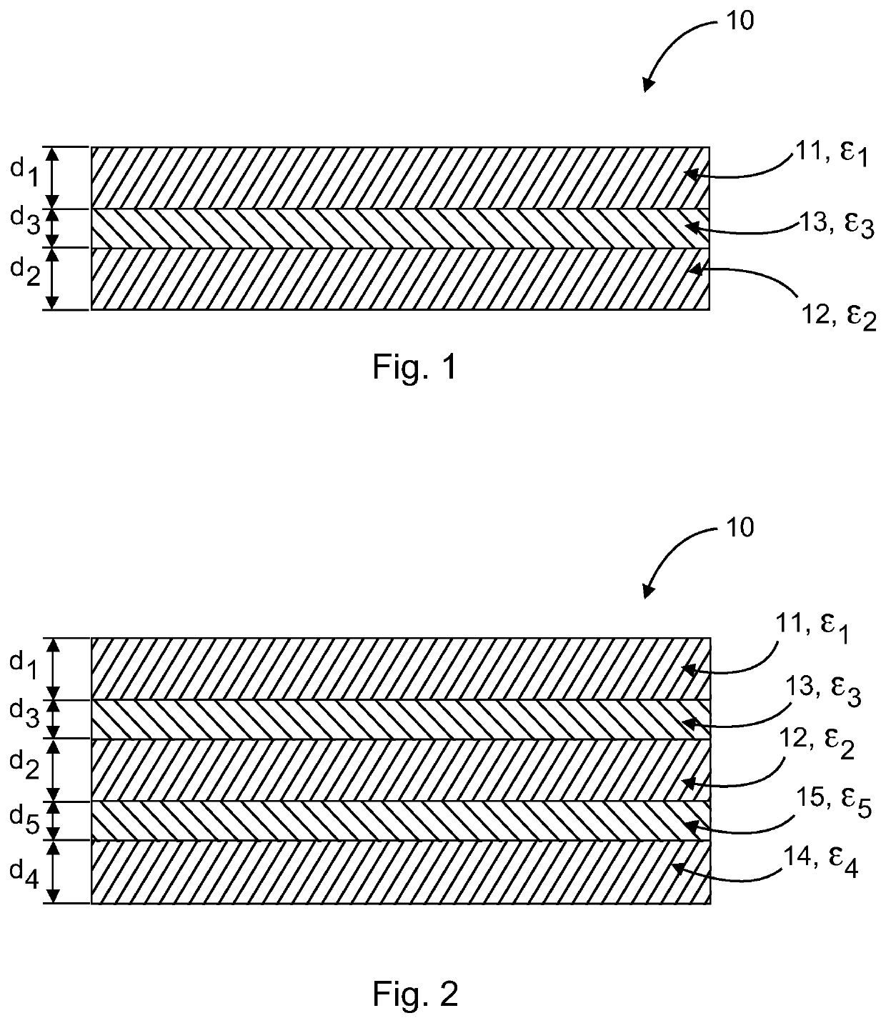
[0050]FIG. 1 shows a schematic sectional illustration of the layers of an asymmetrical radome 10 according to one exemplary embodiment. The radome 10 has a first layer 11 with a first dielectric constant ε1 and a first layer thickness d1, a second layer 12 with a second dielectric constant ε2 and a second layer thickness d2, and a third layer 13 with a third dielectric constant ε3 and a third layer thickness d3. The third layer 13 is arranged between the first layer 11 and the second layer 12 and connects them to one another.

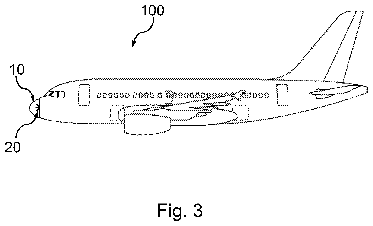
[0051]The first layer 11 corresponds to the outside of the radome, i.e. in FIG. 3 the side facing away from the antenna 20 and the aircraft 100, and is formed from a thermosetting material, in particular from a cyanate ester resin or an epoxy resin reinforced with short or continuous quartz or glass fibers. As a result, the first layer 11 is mechanically very stable and withstands a bird strike or hail, for example, without being permanently deformed or broken. ...


PUM

PropertyMeasurementUnit
dielectric constantaaaaaaaaaa
dielectric constant ε3aaaaaaaaaa
dielectric constants ε1aaaaaaaaaa

Abstract

An asymmetrically constructed radome for an aircraft and an aircraft having an antenna and a corresponding radome are described. The radome has a first layer with a first dielectric constant and a first layer thickness, and a second layer with a second dielectric constant and a second layer thickness. The first layer thickness and the second layer thickness are different from each other. The first layer includes a thermosetting material and the second layer includes a thermoplastic material. Such an asymmetrical radome structure improves the mechanical stability and electromagnetic transparency of the radome.

Description

FIELD OF THE INVENTION[0001]The present disclosure relates to radomes for protecting antennas, in particular for protecting antennas or transmitting and receiving devices mounted on aircraft.BACKGROUND OF THE INVENTION[0002]In order to protect antennas in ground, aviation and space-flight applications from external influences or from environmental influences, use is made of radomes which cover the antenna. Radomes of this type must have the necessary mechanical stability to withstand the loads arising from external influences and must also be as transparent as possible to electromagnetic signals in at least one selected frequency range in order not to influence the functioning of the covered antenna more than necessary. Particularly in aviation applications, radomes must have a high mechanical stability in order, for example, to withstand bird strikes or the high air pressures during flight, ensuring that the antenna is not damaged. For phase-sensitive applications such as, for exam...

Claims


Application Information

Patent Timeline
Patent Type & Authority Applications(United States)
IPC IPC(8): H01Q1/42H01Q1/28
CPCH01Q1/422H01Q1/281
Inventor KARCH, CHRISTIANWOLFRUM, JOHANNES
Owner AIRBUS DEFENCE & SPACE
Why Eureka
Try Eureka