Control device and electric power tool system

Pending Publication Date: 2022-09-29
POSITEC POWER TOOLS (SUZHOU) CO LTD
View PDF0 Cites 0 Cited by
  • Summary
  • Abstract
  • Description
  • Claims
  • Application Information

AI Technical Summary

Benefits of technology

The patent is about a tool and control device that can be used in a variety of tasks. It is small and easy to use, with high efficiency. The technical effect of this patent is to provide a versatility and ease of use for electric power tools and control devices.

Problems solved by technology

Existing electric power tools are usually directly combined with a battery pack, resulting in a large volume of the “combined” electric power tool.
During use, when a user moves a main body of the tool, the battery pack follows the main body of the electric power tool, which is inconvenient to carry and store.
Moreover, when the user operates the electric power tool for an extended time, the tool may become difficult to control, especially for finer operations.

Method used


Image

  • Control device and electric power tool system
  • Control device and electric power tool system
  • Control device and electric power tool system

Examples


Embodiment Construction

[0105]The following clearly and completely describes the technical solutions in the implementations of this application with reference to the accompanying drawings. The described embodiments are merely some but not all of the implementations of this application. All other implementations obtained by a person of ordinary skill in the art based on the embodiments of this application without creative efforts shall fall within the protection scope of this application.

[0106]It is to be noted that, when a component is referred to as “being disposed to” another component, the component may be directly on the another component, or there may be an intermediate component. When a component is considered to be “connected to” another component, the component may be directly connected to the another component, or there may be an intermediate component. The terms “vertical”, “horizontal”, “left”, “right”, and similar expressions used in this specification are only for purposes of illustration but ...


PUM


Abstract

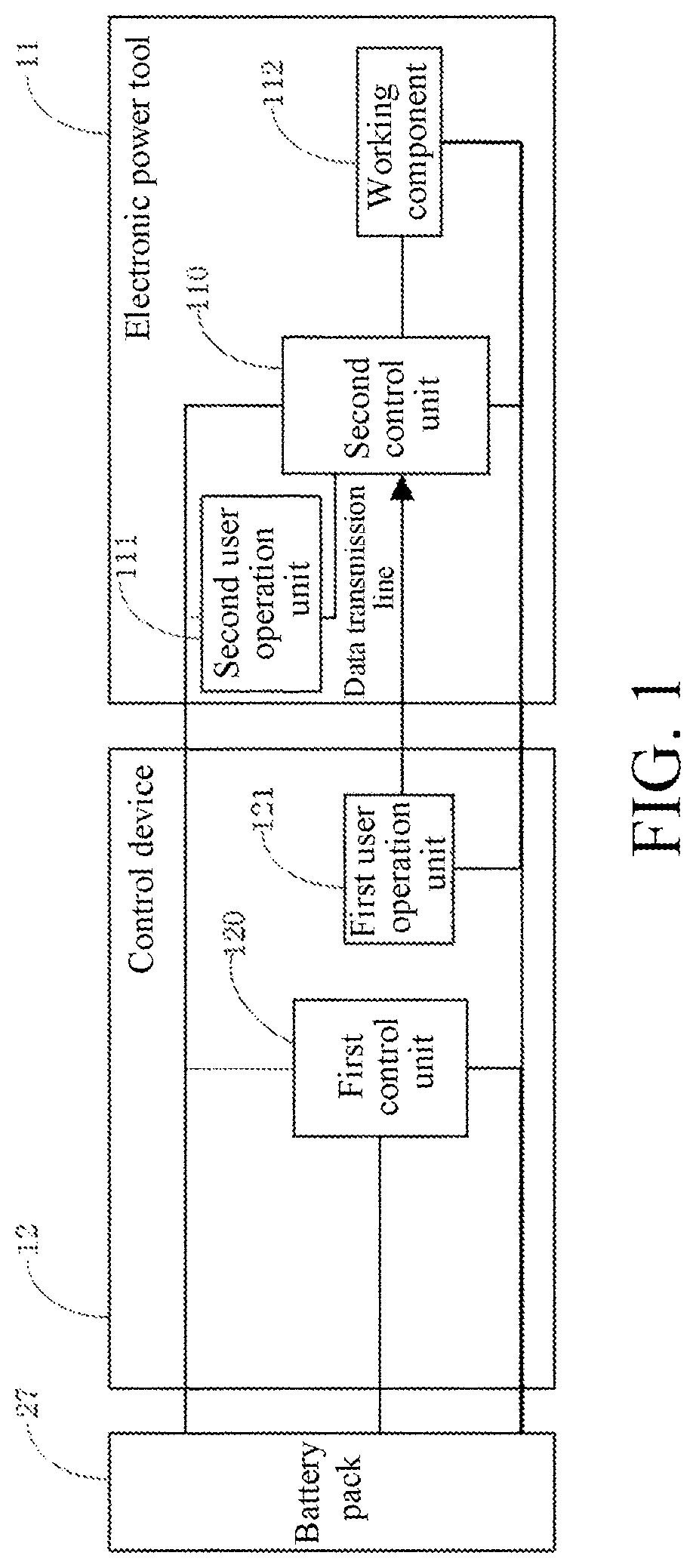
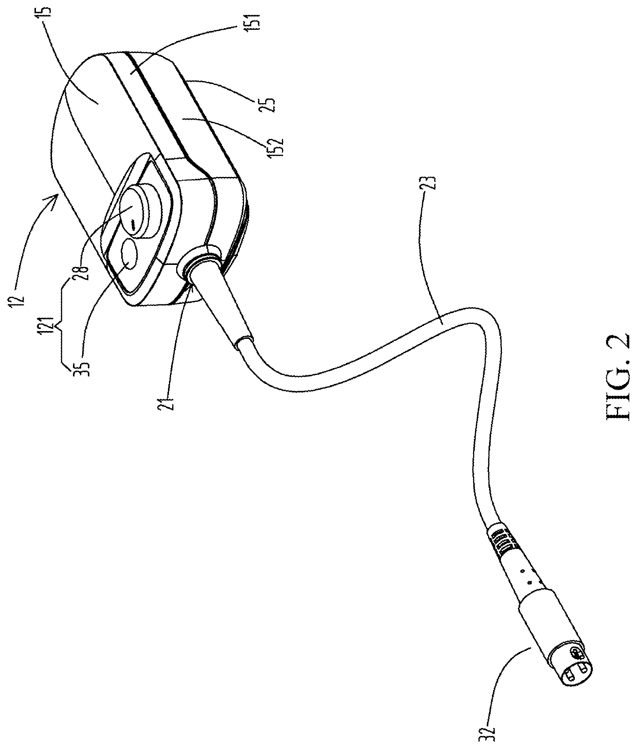
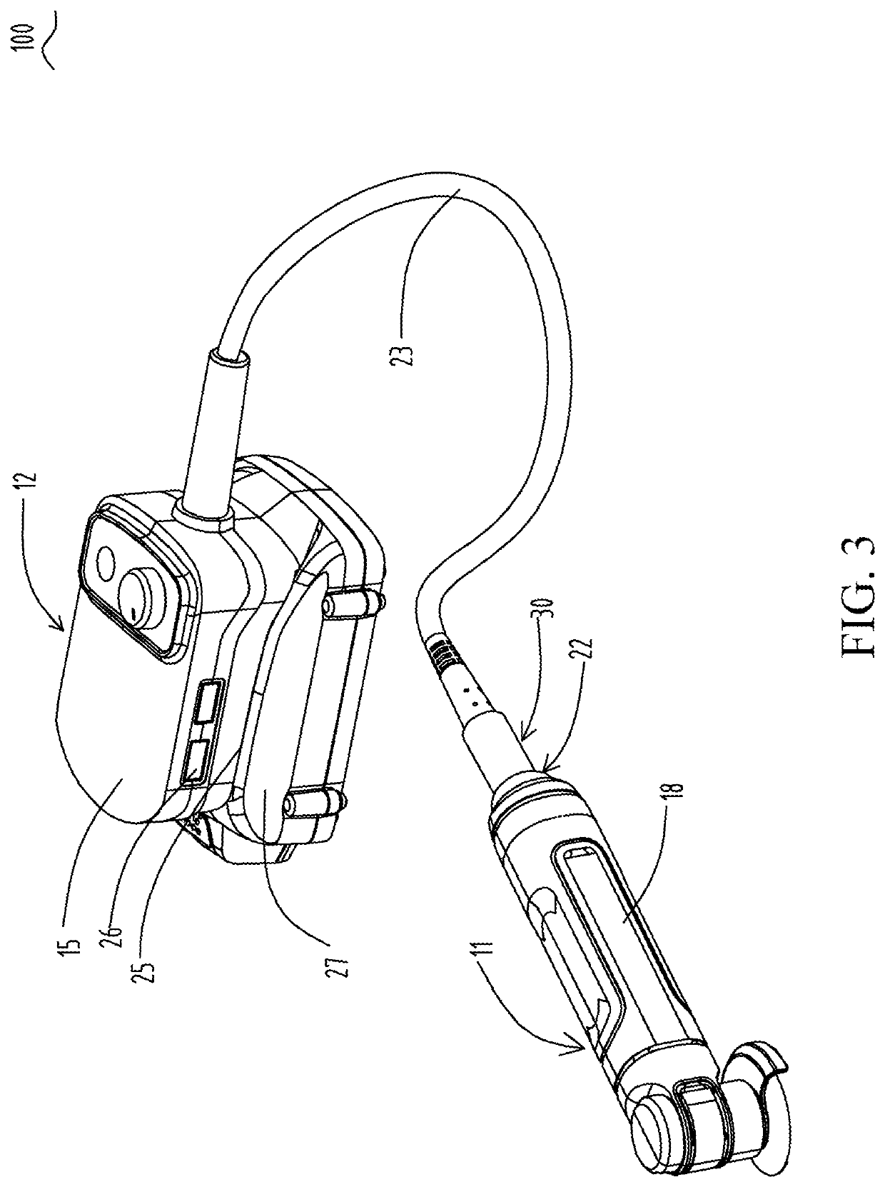
A control device including a first shell; a battery pack mounting part; a first control unit, which is provided in the first shell and is used for cutting off power transmission from a battery pack to an electric power tool when the battery pack is abnormal; a first user operation unit, which is arranged on the first shell and is operated by a user to control the electric power tool; and a first interface, electrically connected to the first user operation unit. An electric power tool system comprises the control device and the electric power tool. The control device can be adapted to different types of electric power tools, and the control device is not provided with a control portion used for adjusting working parameter of the electric power tool, such that the control device can more flexibly match an upgraded new electric power tool.

Description

CROSS-REFERENCE TO RELATED APPLICATIONS[0001]This application is a Continuation of International Application No. PCT / CN2020 / 136188, filed on Dec. 14, 2020, which claims the benefit of Chinese Application Nos. 201922242198.5, filed on Dec. 13, 2019; 202020145329.8, filed on Jan. 22, 2020; 202010851578.3, filed on Aug. 21, 2020; and 202021772666.6, filed on Aug. 21, 2020, the contents of each of which are all hereby incorporated by reference herein in their entirety.BACKGROUNDTechnical Field[0002]The described embodiments herein relate to the field of electric power tools, and in particular, to a control device and an electric power tool system.Related Art[0003]Existing electric power tools are usually directly combined with a battery pack, resulting in a large volume of the “combined” electric power tool. During use, when a user moves a main body of the tool, the battery pack follows the main body of the electric power tool, which is inconvenient to carry and store. Moreover, when th...

Claims


Application Information

Patent Timeline
IPC IPC(8): H02J7/00B25F5/02H01M50/247H01M10/48
CPCH02J7/00304H02J7/0047H02J7/0045B25F5/02H01M50/247H01M10/486H01M10/482H01M2220/30A45D20/08H02J7/0031B23K3/047H01M50/296
Inventor SZOMMER, HARRYBROWN, WARRENGERHARDT, GRAHAMPANG, XIAOLILIANG, BINGLU, JUNYANG, ZHIHAN
Owner POSITEC POWER TOOLS (SUZHOU) CO LTD
Why Eureka
Try Eureka