
Automobile suspension device

a suspension device and automobile technology, applied in the direction of suspension arms, suspension components, resilient suspensions, etc., can solve the problem of the mounting angle limitation of the damper, and achieve the effect of reducing geometric changes, preventing deformation of the front and rear wall surfaces, and increasing the area of the wall surfa

Active Publication Date: 2022-10-06
MAZDA MOTOR CORP
View PDF14 Cites 2 Cited by
  • Summary
  • Abstract
  • Description
  • Claims
  • Application Information

AI Technical Summary

Benefits of technology

The present patent text describes an automobile suspension device that reduces sliding friction while ensuring road clearance. Specifically, the device includes a lower arm that supports the lower end of a damper. The damper mounting portion is located lower than the pivot of the lower arm and the pivot on the vehicle-body side of the lower arm, which allows the damper to stand vertically and reduces the inclination angle of the damper. Ribs are added to prevent deformation of the front and rear wall surfaces, which also increases the area of the damper mounting portion and stabilizer-link mounting portion. The device includes a 5-link suspension system and uses the lower arm to support the damper. Overall, the device reduces sliding friction and improves the performance of the automobile suspension system.

Problems solved by technology

However, when the lower end of the damper is mounted to the lower arm, it is necessary to set the geometry of the lower arm and the damper while ensuring a road clearance for the lower arm, and thus there is a layout limitation for the mounting angle of the damper.

Method used


Image

  • Automobile suspension device
  • Automobile suspension device
  • Automobile suspension device

Examples


Embodiment Construction

[0024]Hereinafter, an automobile suspension device according to an embodiment of the present disclosure will be described with reference to the attached drawings.

[0025]The embodiment of the present disclosure will be described hereinafter based on the drawings.

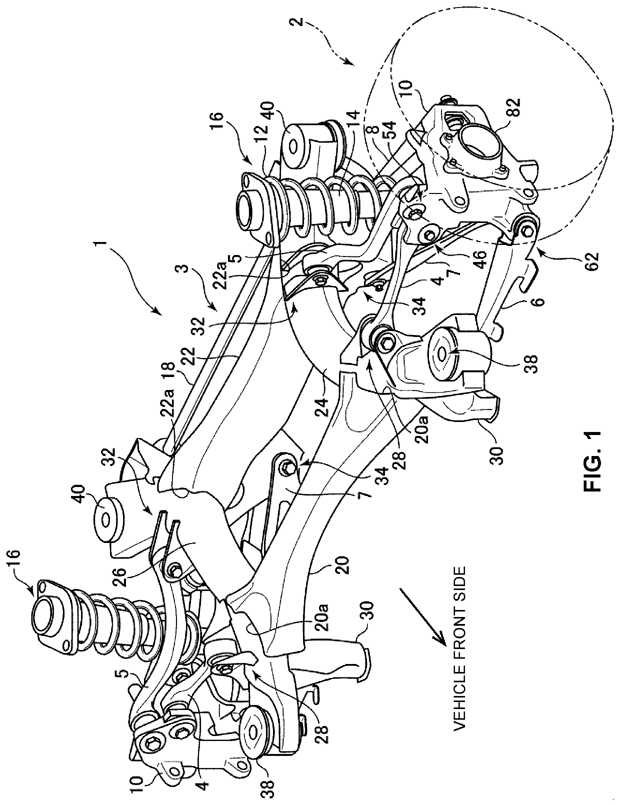
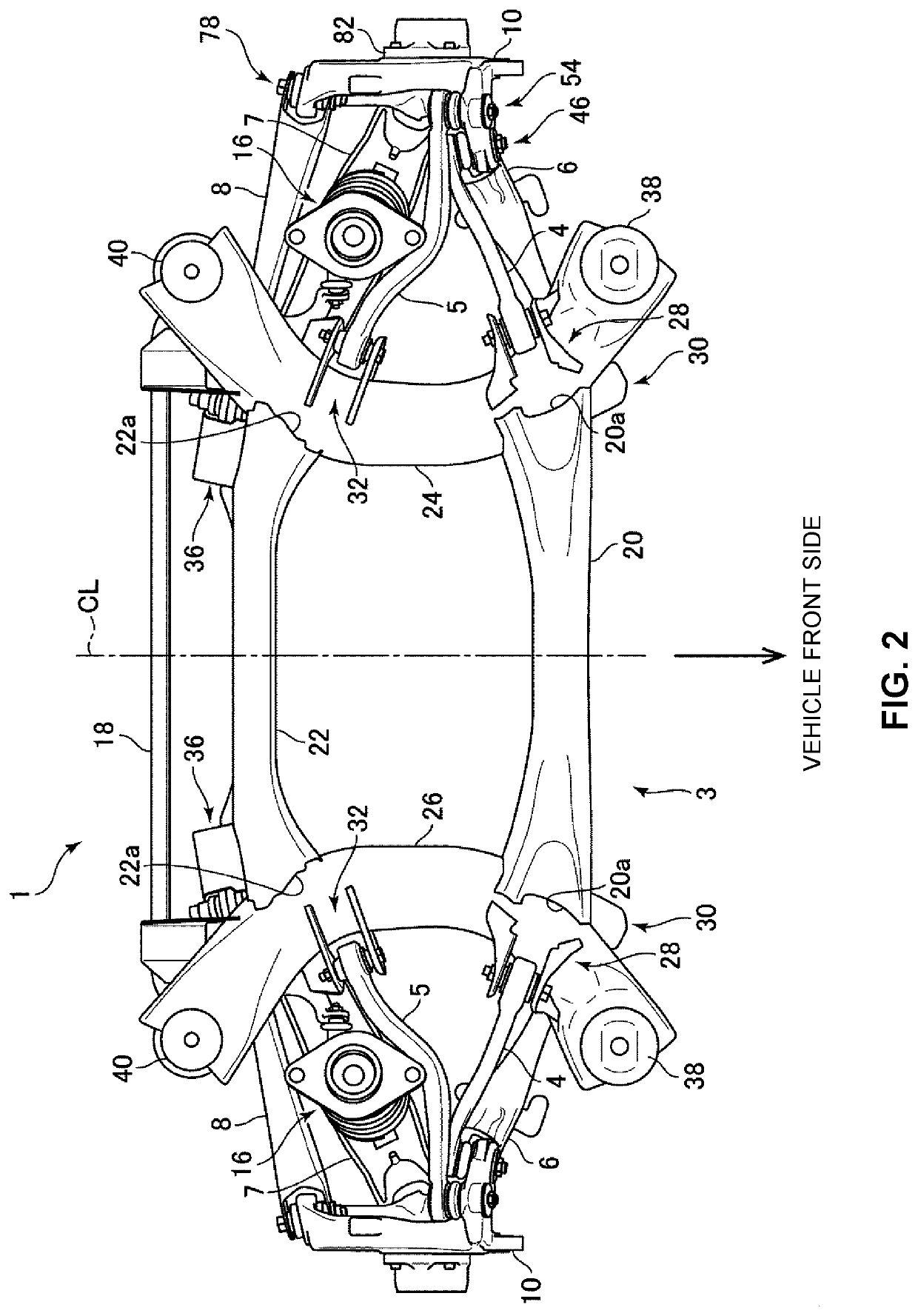
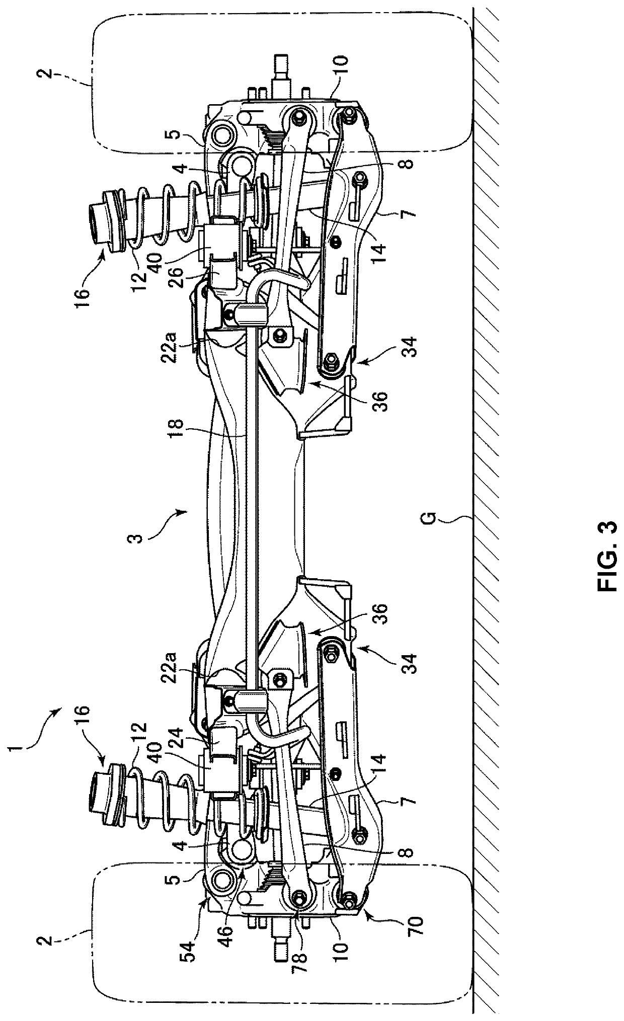
[0026]First, an overall configuration of the automobile suspension device according to the embodiment of the present disclosure will be described using FIG. 1 to FIG. 3. FIG. 1 to FIG. 3 show the embodiment in which a rear wheel suspension device 1 (hereinafter simply referred to as the rear suspension) for an automobile according to the embodiment of the present disclosure is applied to each of left and right wheels of the automobile, wherein FIG. 1 is a perspective view of a rear suspension assembly of the automobile to which the automobile suspension device according to the embodiment of the present disclosure is applied, FIG. 2 is a top view of the rear suspension assembly shown in FIG. 1, and FIG. 3 is a rear view of the ...


PUM


Abstract

A five-link automobile suspension device is configured to support a lower end of a damper with a lower arm, and is capable of reducing sliding friction while ensuring a road clearance. Embodiments include a lower arm connecting a wheel support and a vehicle body, and a damper that has a lower end connected to the lower arm and is disposed to incline upward toward a vehicle-width-direction inner side in a rear view. A wall surface of the lower arm has a damper mounting portion, which supports a pivot of the damper, at a position lower than a straight line connecting a pivot on a wheel side and a pivot on a vehicle-body side of the lower arm. A bottom surface of the lower arm has a bulge formed at a position under the damper mounting portion.

Description

TECHNICAL FIELD[0001]The present disclosure relates to an automobile suspension device, and more particularly relates to a rear wheel multi-link suspension constituted by five I-links.BACKGROUND ART[0002]Conventionally, there has been known a multi-link suspension having five I-links (hereinafter referred to as “arms”), wherein each arm's vehicle-body-side end is connected to a vehicle body, and each arm's wheel-side end is connected to a wheel support (hub carrier) that supports a wheel. Such a multi-link suspension having five arms has high performance potential because it is possible to arrange the respective arms so as to be optimally restrained according to requirements for the degree of freedom of five motions except for an up and down stroke of a rear wheel.[0003]In recent years, there is a known configuration of such a multi-link suspension in which a lower end of a damper as a shock absorber is connected to a lower arm among the five arms (see, for example, Published Intern...

Claims


Application Information

Patent Timeline
IPC IPC(8): B60G3/18
CPCB60G3/18B60G7/006B60G13/005B60G2200/18B60G3/20B60G2200/156B60G7/001
Inventor OKUYAMA, KAZUHIROHIRAMATSU, MASAYA
Owner MAZDA MOTOR CORP
Learn More