Electronic payment system, electronic payment method, and information storage medium
a technology of electronic payment and electronic payment, applied in the field of electronic payment system, electronic payment method, information storage medium, can solve the problem that the convenience of users cannot be sufficiently enhanced, and achieve the effect of enhancing the convenience of electronic paymen
- Summary
- Abstract
- Description
- Claims
- Application Information
AI Technical Summary
Benefits of technology
Problems solved by technology
Method used
Image
Examples
modification examples
5. Modification Examples
[0163]The present disclosure is not limited to the at least one embodiment described above, and can be modified suitably without departing from the spirit of the present disclosure.
[0164]FIG. 13 is an example of a functional block diagram in the modification examples. In the modification examples described below, each of functions illustrated in FIG. 13 is implemented. Each of a reliability level acquisition module 104, a notification module 105, a receipt output module 106, a usage amount acquisition module 107, an information providing module 108, and a permission module 109 is implemented mainly by the control unit 11. An execution instruction reception module 402 is implemented mainly by the control unit 41.
modification example 1
5-1. Modification Example 1
[0165]For example, the electronic payment system S may further include the reliability level acquisition module 104 for acquiring a reliability level of a user in electronic payment. The reliability level is an index indicating reliability of the user in the electronic payment. As the probability that the electronic payment may be completed normally becomes higher, the reliability level becomes higher. For example, in the case of the credit card payment, the reliability level acquisition module 104 acquires the reliability level of the user held by a credit card company. This reliability level is so-called credibility information. Credibility information held by another payment service provider of, for example, electronic money may be acquired as the reliability level. A malicious user may commit a fraud, and hence the user may be more liable to commit a fraud as the reliability level becomes lower. The reliability level can also be said to be a degree of ...
modification example 2
5-2. Modification Example 2
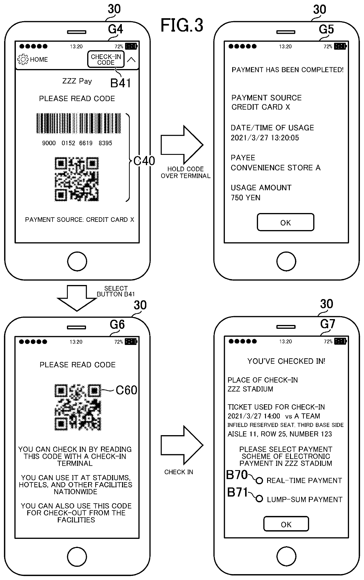
[0171]FIG. 14 is a view for illustrating an example of the electronic payment system S according to Modification Example 2 of the present disclosure. The determination module 101 in Modification Example 2 determines whether to execute the real-time payment or the lump-sum payment each time a payment request is received. As illustrated in FIG. 14, a selection screen G11 for selecting any one of the real-time payment or the lump-sum payment is displayed each time the user holds the code C40 over the payment terminal 50 instead of the user selecting the real-time payment or the lump-sum payment at the time of the check-in.
[0172]The user can select the real-time payment by selecting a button B110. The user can select the lump-sum payment by selecting a button B111. Each time a payment request is received, the determination module 101 determines whether to execute the real-time payment or the lump-sum payment based on a result of the selection on the selection ...
PUM
 Abstract
Description
Claims
Application Information
 - R&D
- Intellectual Property
- Life Sciences
- Materials
- Tech Scout
- Unparalleled Data Quality
- Higher Quality Content
- 60% Fewer Hallucinations
Browse by: Latest US Patents, China's latest patents, Technical Efficacy Thesaurus, Application Domain, Technology Topic, Popular Technical Reports.
© 2025 PatSnap. All rights reserved.Legal|Privacy policy|Modern Slavery Act Transparency Statement|Sitemap|About US| Contact US: help@patsnap.com


