Connecting device and assembly of connecting device and mating device

a technology of connecting device and assembly, which is applied in the direction of coupling device connection, coupling/disengagement coupling parts, four or more pole connections, etc., can solve the problems of poor electrical transmission, corresponding terminals may easily deviate from each other, etc., and achieve better floating effect and better electrical transmission

Active Publication Date: 2022-10-06
NEXTRONICS ENG CORP
View PDF11 Cites 0 Cited by
  • Summary
  • Abstract
  • Description
  • Claims
  • Application Information

AI Technical Summary

Benefits of technology

[0005]In response to the above-referenced technical inadequacy, the present disclosure provides a connecting device and an assembly of the connecting device and a mating device. When the connecting device is mated with the mating device, a better floating effect and a guiding effect can be provided. Terminals of the connecting device are firmly mated with the corresponding terminals of the mating device, so that the corresponding terminals are firmly in contact with each other, resulting in a better electrical transmission.
[0008]Therefore, one of the beneficial effects of the present disclosure is that, the connecting device of the assembly of the connecting device and the mating device provided by the present disclosure includes the insulating main body, the plurality of terminals, the magnet set, the inner housing, the crown leaf spring, the outer housing, and the wave spring. The crown leaf spring has the ring body and the plurality of elastic parts, and the plurality of elastic parts are disposed on the ring body at intervals. The crown leaf spring is disposed on the inner housing, and the plurality of elastic parts of the crown leaf spring abut the outer housing. The wave spring is disposed between the inner housing and the outer housing, such that the insulating main body, the plurality of terminals, the magnet set, and the inner housing are held on the outer housing by the crown leaf spring and the wave spring to form the floating member. When the connecting device is mated with the mating device, the effects of floating and guiding can be provided. The crown leaf spring can be used to hold the inner housing, such that the inner housing is disposed on the outer housing in a floating way. The plurality of elastic parts surround the inner housing, so as to abut the outer housing, thereby forming a multi-point support. In addition, the inner housing is held and disposed on the outer housing in the floating way through the cooperation of the wave spring and the crown leaf spring, so as to achieve better effects of floating and guiding. Accordingly, the terminals of the connecting device are firmly mated with the corresponding terminals of the mating device, so that the corresponding terminals are firmly in contact with each other, resulting in the better electrical transmission.

Problems solved by technology

Although the insulating main body and the terminals can be disposed in the conventional connecting device in the floating manner, the corresponding terminals may easily deviate from each other when the connecting device is mated with the mating device.
Accordingly, the corresponding terminals cannot be firmly in contact with each other, resulting in poor electrical transmission.

Method used


Image

  • Connecting device and assembly of connecting device and mating device
  • Connecting device and assembly of connecting device and mating device
  • Connecting device and assembly of connecting device and mating device

Examples


first embodiment

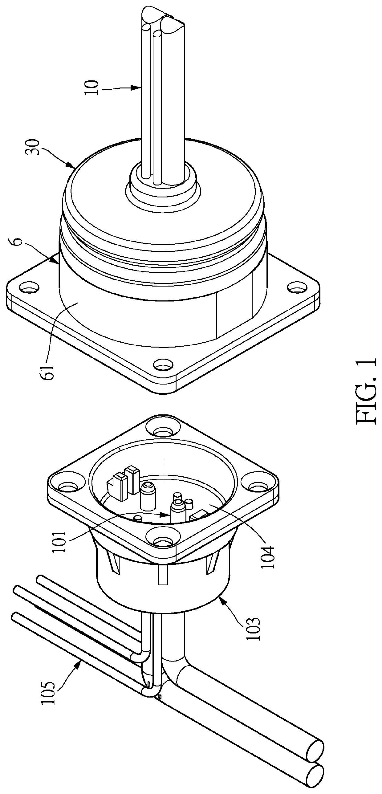
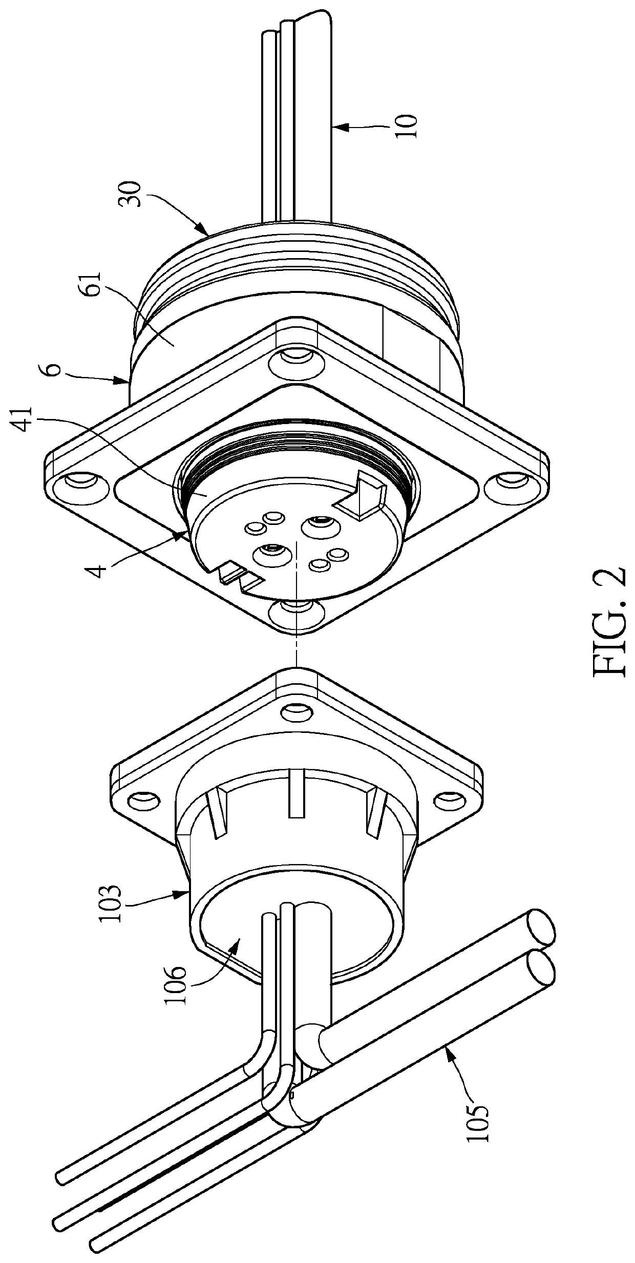
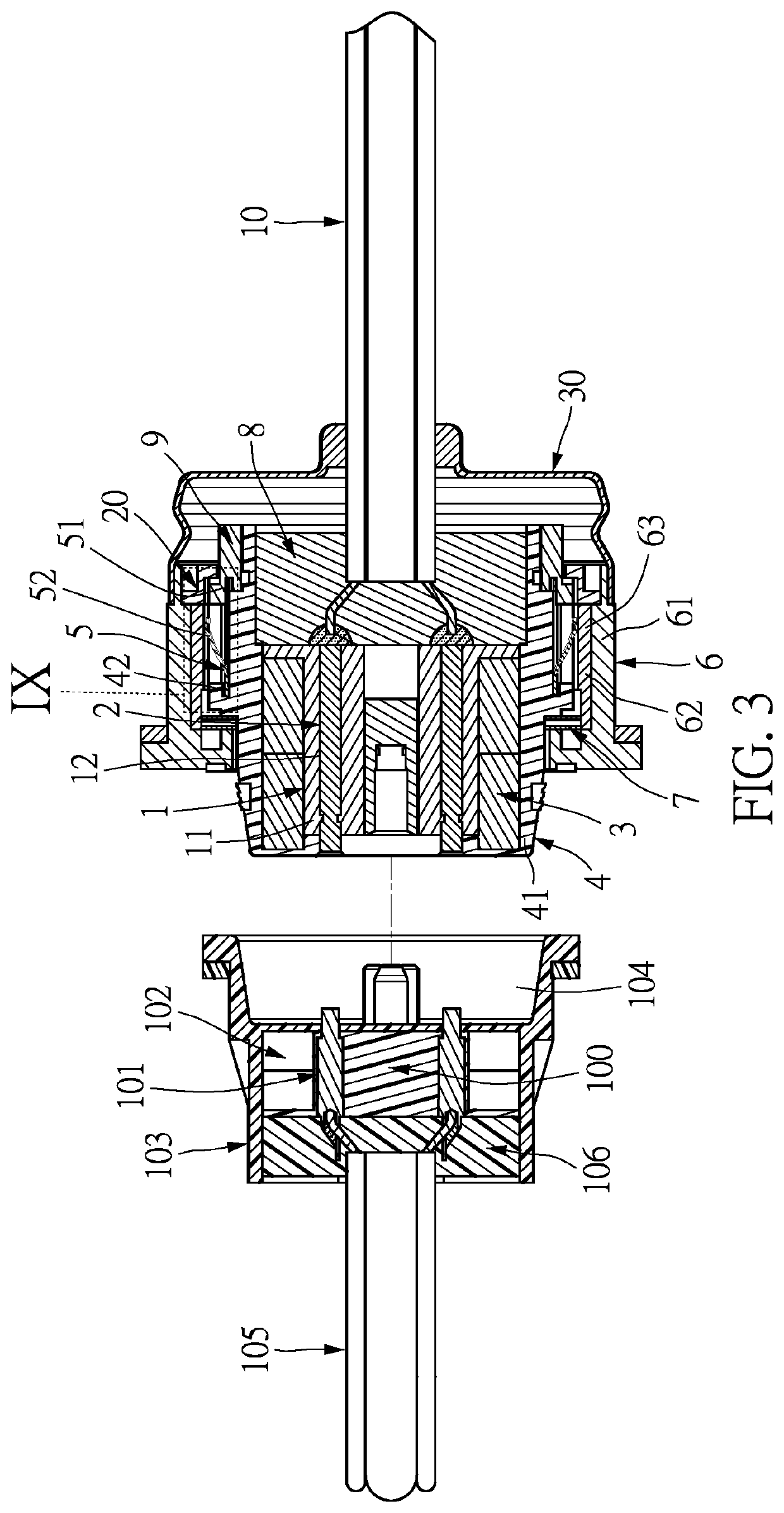
[0024]Referring to FIG. 1 to FIG. 4, which is to be read in conjunction with FIG. 5 and FIG. 6, the present disclosure provides a connecting device, which can be mated with a mating device (i.e., a connector). The connecting device includes an insulating main body 1, a plurality of terminals 2, a magnet set 3, an inner housing 4, a crown leaf spring 5, an outer housing 6, and a wave spring 7.

[0025]In the present disclosure, a “front end” refers to an end toward the mating device (i.e., the connector), and a “rear end” refers to an end away from the mating device (i.e., the connector), that is, an end toward a mating direction is defined as the “front end”, and an end away from the mating direction is defined as the “rear end”.

[0026]The insulating main body 1 is made of a plastic material and is an insulator. The insulating main body 1 can have a main body part 11 and a plurality of terminal holes 12, and the main body part 11 can be cylindrical in shape. The plurality of terminal ho...


PUM


Abstract

A connecting device and an assembly of the connecting device and a mating device are provided. The connecting device includes an insulating main body, a plurality of terminals, a magnet set, an inner housing, a crown leaf spring, an outer housing, and a wave spring. The plurality of terminals are disposed on the insulating main body, the magnet set is disposed on the insulating main body, and the inner housing is sleeved around the insulating main body. The wave spring and the crown leaf spring are each disposed between the inner housing and the outer housing, and abut the inner housing, so that the insulating main body, the plurality of terminals, the magnet set, and the inner housing are arranged in a floating state.

Description

CROSS-REFERENCE TO RELATED PATENT APPLICATION[0001]This application claims the benefit of priority to China Patent Application No. 202110339627.X, filed on Mar. 30, 2021 in People's Republic of China. The entire content of the above identified application is incorporated herein by reference.[0002]Some references, which may include patents, patent applications and various publications, may be cited and discussed in the description of this disclosure. The citation and / or discussion of such references is provided merely to clarify the description of the present disclosure and is not an admission that any such reference is “prior art” to the disclosure described herein. All references cited and discussed in this specification are incorporated herein by reference in their entireties and to the same extent as if each reference was individually incorporated by reference.FIELD OF THE DISCLOSURE[0003]The present disclosure relates to a connecting device and an assembly of a connecting device...

Claims


Application Information

Patent Timeline
Patent Type & Authority Applications(United States)
IPC IPC(8): H01R13/627H01R13/62H01R9/22H01R9/03
CPCH01R13/6277H01R13/6205H01R9/223H01R9/03H01R13/6315H01R24/005H01R13/5205H01R2107/00
Inventor ZHANG, YONGLIANG, LIANG-JU
Owner NEXTRONICS ENG CORP
Why Eureka
Try Eureka