Anemometry tower provided with laser anemometer

A technology of wind measuring tower and wind measuring instrument, applied in the field of wind measuring tower, can solve the problems of low stability of wind measuring tower, complicated construction, prone to tilt or swing, etc., and achieve the authenticity, reliability, stability and firmness of measured data Good, the effect of reducing the production cost

Inactive Publication Date: 2013-12-25
郑俊斌
View PDF7 Cites 0 Cited by
  • Summary
  • Abstract
  • Description
  • Claims
  • Application Information

AI Technical Summary

Problems solved by technology

The existing wind-measuring towers generally use basic structures such as tripods, steel skirt piles or PHC skirt piles in China, and PHC skirt piles, single piles, jackets, floating and other basic structures are generally used internationally. The shortcomings of these wind-measuring towers are: The structure is complex and the construction is complicated, and the tower body is a fixed structure, its height is generally 30-40 meters, the cost of each tower is generally about 15 million yuan, and the construction period is long, usually about 1 year.
And some have low strength against extreme conditions in the ocean. When the force is complex, the stability of the wind measuring tower is low, and it is prone to tilt or swing, which makes the accuracy of wind measurement poor.
Although the recently disclosed steel row-type negative measuring tower foundation and wind measuring tower have some advantages, they still have shortcomings such as complicated manufacturing and positioning, low resistance to wind flow, etc., and it is difficult to install a laser wind measuring instrument with high requirements

Method used


Image

  • Anemometry tower provided with laser anemometer
  • Anemometry tower provided with laser anemometer
  • Anemometry tower provided with laser anemometer

Examples


Embodiment Construction

[0009] The present invention will be further described with reference to the accompanying drawings and examples.

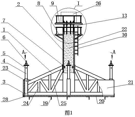
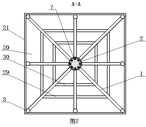
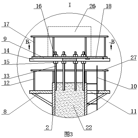
[0010] The structure shown in the embodiment of the present invention is only one of the implementations of the wind measuring tower described in the present invention. The main structure of the wind measuring tower provided by the present invention has a wind measuring tower foundation, the tower body is installed on the wind measuring tower foundation, the adjustable platform is installed on the tower body top, the laser anemometer is installed on the adjustable platform, and the height of the wind measuring tower is About 13.5 meters. The specific structure of the wind measuring tower of the present invention comprises: the foundation of the wind measuring tower, this foundation has a base plate 20, the side plate 21 is connected on the peripheral wall of the base plate 20, the base plate 20 and the side plate 21 are connected to form a box structure, the base ...


PUM


Abstract

The invention discloses an anemometry tower provided with a laser anemometer, which comprises a foundation of the anemometry tower. The foundation is provided with a bottom plate, side plates are connected on the peripheral walls of the bottom plate, the bottom plate and the side plates are connected to form a box type structure, a plurality of longitudinal supporting rods in the perpendicular and horizontal direction are mounted on the bottom plate, inclined supporting rods are connected among the longitudinal supporting rods, a tower body is mounted at the center of the bottom plate, an adjustable platform is mounted on the upper portion of the tower body and provided with a platform plate, a lead screw is mounted on the platform plate, one end of the lead screw is connected with the tower body, a main inclined supporting rod is mounted among the tower body and the side plates at least, positioning piles are mounted on the periphery of the bottom plate and are connected with one ends of the main inclined supporting rods, and the other ends of the main inclined supporting rods are connected with the tower body. The laser anemometer can be mounted on the anemometry tower, the anemometry tower is short in manufacturing cycle and low in manufacturing cost and is fine in stability after being positioned and sunk, the platform of the anemometry tower can be adjusted horizontally, the laser anemometer can be stably mounted on the platform of the anemometry tower, and acquisition of accurate data of anemometry can be guaranteed.

Description

technical field [0001] The invention relates to a wind measuring tower, which is a wind measuring tower equipped with a laser wind measuring instrument. Background technique [0002] The technical scheme of using wind energy to generate electricity has been continuously researched and developed in various countries. Since the construction of wind power generation devices in open areas can achieve better power generation effects, the unique characteristics of wind direction stability, wind flow intensity and wind speed at sea make the construction of wind power generation devices at sea has become the main research aspect of wind power generation in various countries one. Before building a wind farm at sea, it is necessary to build an offshore wind measuring tower in the sea area where the wind farm is planned to obtain actual wind resource data and related meteorological data, so as to determine whether the sea area is suitable for the construction of an offshore wind farm...

Claims


Application Information

Patent Timeline
Patent Type & Authority Patents(China)
IPC IPC(8): E02D27/42E04H12/14
Inventor 郑俊斌
Owner 郑俊斌
Why Eureka
Try Eureka