
A method for controlling charging of electrical storage devices

a technology for electrical storage devices and charging methods, applied in the direction of secondary cell servicing/maintenance, battery/fuel cell control arrangement, etc., can solve the problems of tripping of grid components, new responsibility and challenges for distribution system operators and transmission system operators, and threatening the reliability of power grid operation

Pending Publication Date: 2022-10-27
VESTAS WIND SYST AS
View PDF0 Cites 0 Cited by
  • Summary
  • Abstract
  • Description
  • Claims
  • Application Information

AI Technical Summary

Benefits of technology

The invention provides a method for controlling charging of at least one electrical storage device that ensures grid stability while allowing for higher penetration of renewable energy in a power grid. Additionally, the method improves the quality of ancillary service provided by the at least one electrical storage device.

Problems solved by technology

The reliability of power grid operation is threatened by the shift towards a high share of converter connected distributed energy resources (DERs) replacing conventional power plants.
The transition towards a higher share of DERs and renewable energy resources brings new responsibility and challenges to the distribution system operators and the transmission system operators.
This may result in tripping of grid components, especially imbedded renewable energy resources, such as wind turbines or photovoltaic panels, conventional generation pole slipping and cascade tripping.
Furthermore, higher frequency deviations, such as nadirs and / or zeniths, may occur, potentially leading to load shedding, and in the worst case power grid collapse.
However, with a lower share of conventional power plants with a high inertia, the power grid is to a greater extent prone to changes in the operating conditions of the power grid, and therefore there is a need for alternative methods of stabilising power grids in case of faults and contingencies in the power grid.

Method used


Image

  • A method for controlling charging of electrical storage devices
  • A method for controlling charging of electrical storage devices
  • A method for controlling charging of electrical storage devices

Examples


first embodiment

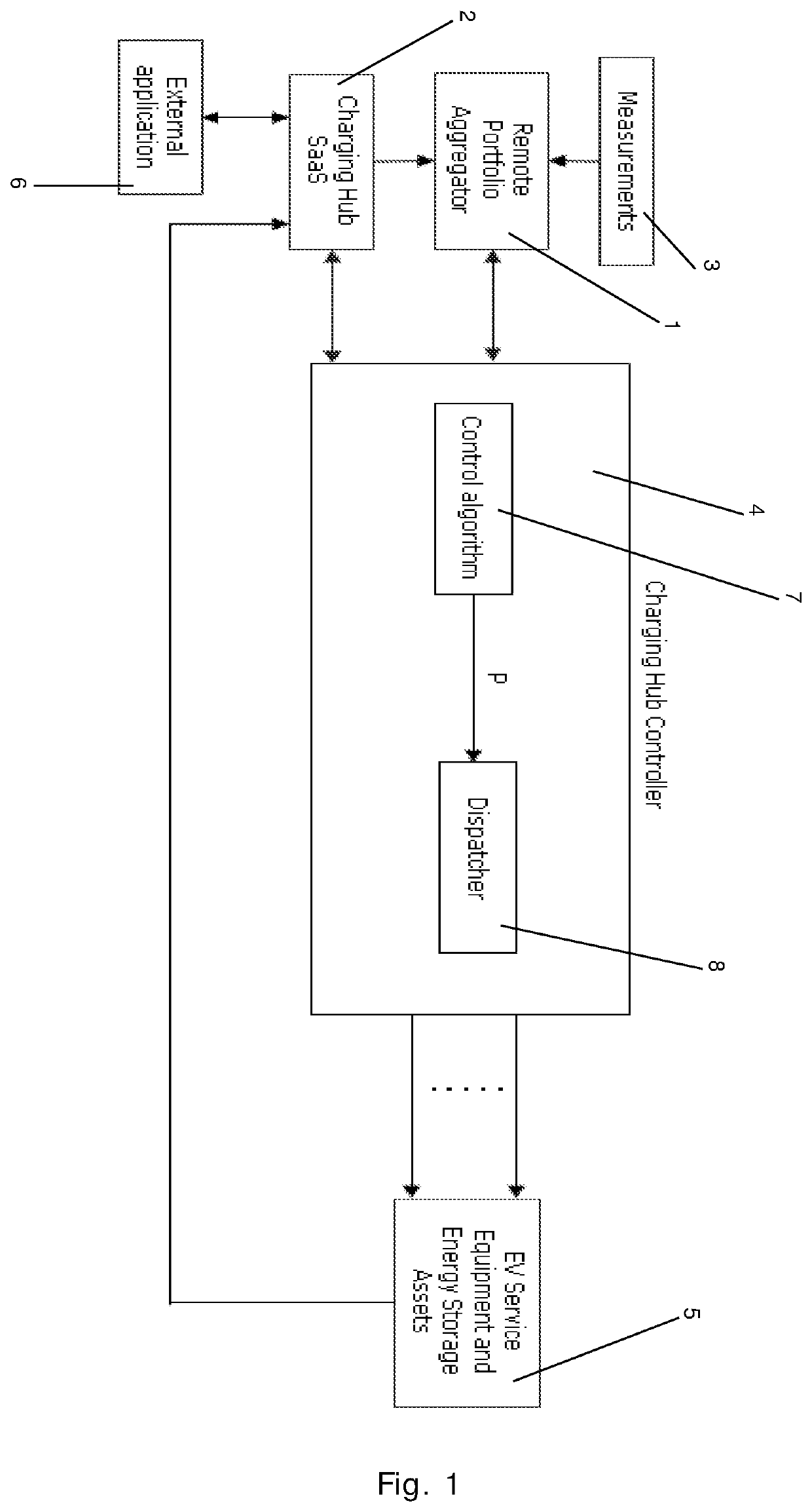
[0115]FIG. 1 is a block diagram illustrating a method according to the invention,

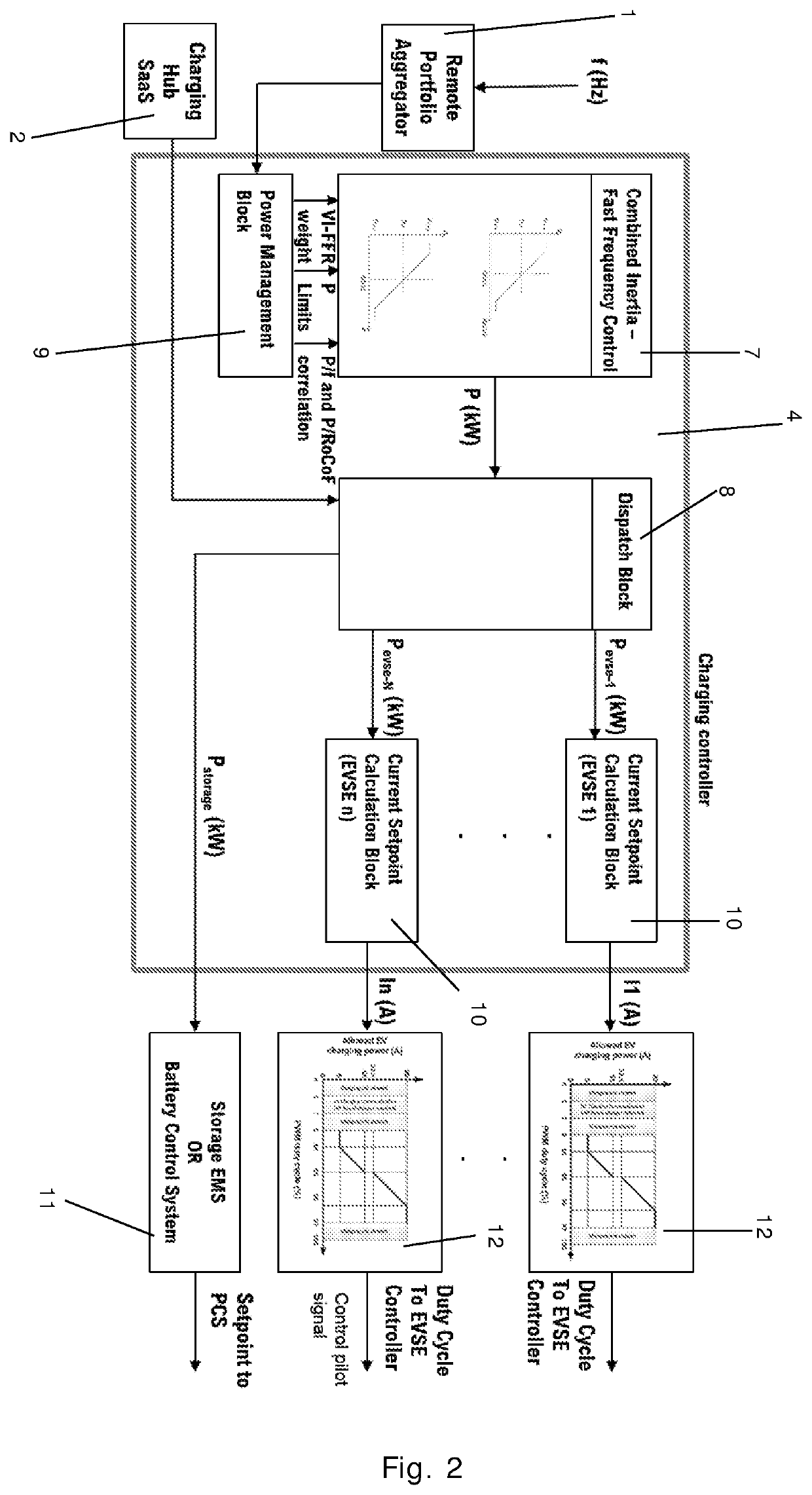
[0116]FIG. 2 is a block diagram illustrating a method according to a second embodiment of the invention,

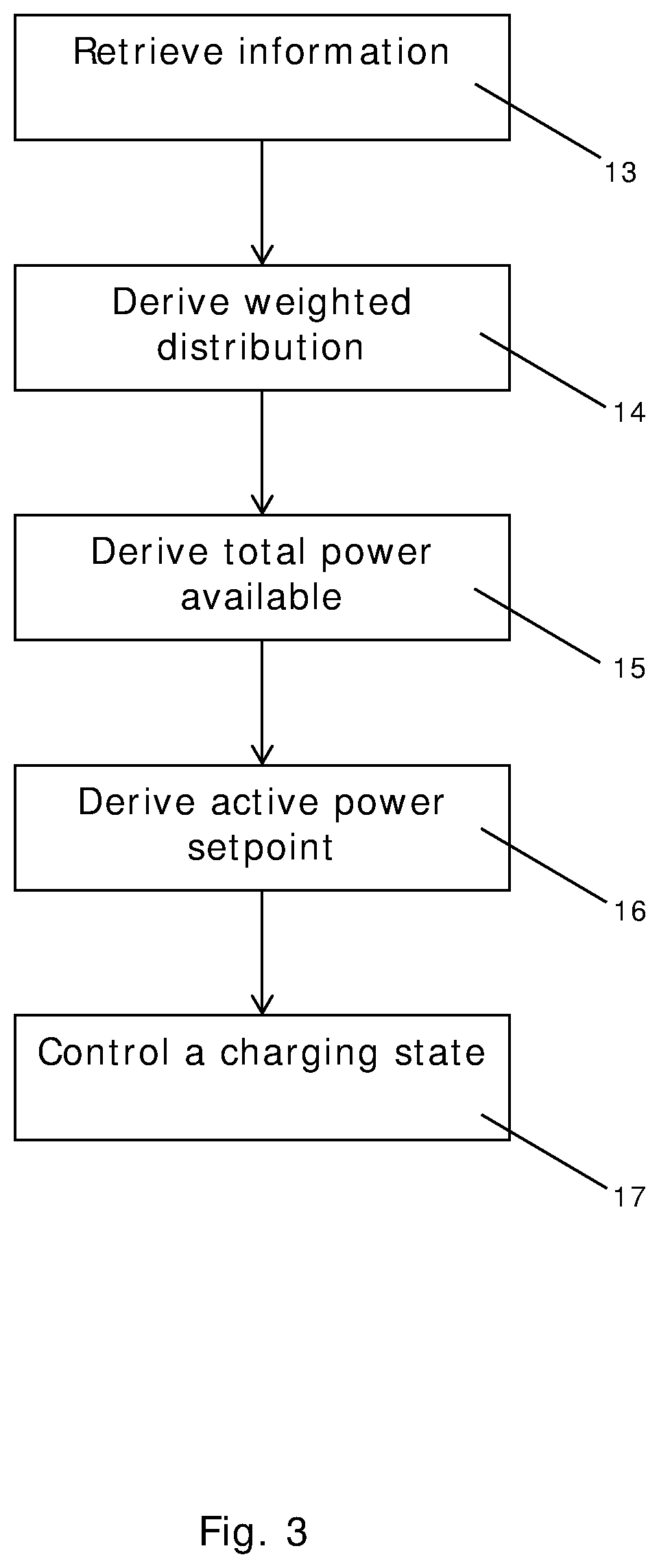
[0117]FIG. 3 is a flow chart illustrating a method according to an embodiment of the invention,

[0118]FIG. 4 is a schematic diagram illustrating a system according to an embodiment of the invention,

[0119]FIG. 5 is a block diagram illustrating a method according to an embodiment of the invention, and

[0120]FIG. 6 is a diagrammatic illustration of a method according to an embodiment of the invention.


PUM


Abstract

A method for controlling charging of at least one electrical storage device is disclosed. Information regarding a power grid and the at least one electrical storage device is used by an aggregator to derive a weighted distribution of virtual inertia response and fast frequency response to be provided to the power grid by the electrical storage devices. A total power available for charging the at least one electrical storage device is derived in accordance with the weighted distribution by a charging controller. An active power setpoint is derived for each of the at least one electrical storage device on the basis of at least (i) the total available power and (ii) the information regarding the at least one electrical storage device. Finally, a charging state of each of the at least one electrical storage device is controlled based on the derived active power setpoint.

Description

FIELD OF THE INVENTION[0001]The present invention relates to a method for controlling charging of at least one electrical storage device, such as an electric vehicle. Furthermore, the present invention relates to a system for charging such an electrical storage device.BACKGROUND OF THE INVENTION[0002]The reliability of power grid operation is threatened by the shift towards a high share of converter connected distributed energy resources (DERs) replacing conventional power plants. The transition towards a higher share of DERs and renewable energy resources brings new responsibility and challenges to the distribution system operators and the transmission system operators. Frequency support will need to be provided by DERs and renewable energy resources connected to the distribution grid. The displacement of conventional generation by inertia-less resources, such as converter connected renewable energy resources, entails an increasing upsurge in the requirement for balancing and syste...

Claims


Application Information

Patent Timeline
IPC IPC(8): B60L53/63H02J7/00H02J3/24H02J3/32B60L53/67B60L53/62B60L53/66H01M10/44
CPCB60L53/63H02J7/00032H02J7/00712H02J7/0013H02J3/241H02J3/322B60L53/67B60L53/62B60L53/66H01M10/441H01M10/44H01M2220/20H02J3/28H02J3/32B60L53/14B60L53/52B60L53/51B60L53/68B60L58/12Y04S10/126Y04S30/12Y02T10/70Y02T10/7072Y02T90/12Y02T90/14Y02T90/16Y02T90/167Y02E60/00Y02E60/10
Inventor REZKALLA, MICHEL MAHER NAGUIBRAGHUCHANDRA, KARTHIKEYA BALLADI
Owner VESTAS WIND SYST AS
Learn More