
Power transmission chain

a transmission chain and power technology, applied in the direction of driving chains, transportation and packaging, gearing, etc., can solve the problems of not always in optimum engagement between formations and teeth, not being able to efficiently transmit the drive, and the known power transmission chain not working efficiently for both drive members

Active Publication Date: 2022-10-27
NEW MOTION LABS LTD
View PDF5 Cites 0 Cited by
  • Summary
  • Abstract
  • Description
  • Claims
  • Application Information

AI Technical Summary

Benefits of technology

The present invention aims to reduce the problem of power transmission chains collapsing inwardly or outwardly due to the weight and pressure of the load being driven. The invention provides a power transmission chain with end portions that have a contact section and a restriction section, which prevent the chain from collapsing inwardly or outwardly. The contact sections can be on the inside or outside of the chain, and may be made of flexible materials that are not strong enough for the remainder of the chain. This construction facilitates the correct engagement of the contact sections and reduces noise and vibration. The invention allows for the chain and drive member to be the same size or smaller, and can be manufactured a lot smaller than known prior chains and sprocket arrangements.

Problems solved by technology

The known power transmission chains are such that they do not transmit drive as efficiently as would be desired.
With the different diameters and the different numbers of teeth, the engaging formations and the teeth are not always in optimum engagement.
The result is that the known power transmission chains do not work efficiently for both drive members.

Method used


Image

  • Power transmission chain
  • Power transmission chain
  • Power transmission chain

Examples


Embodiment Construction

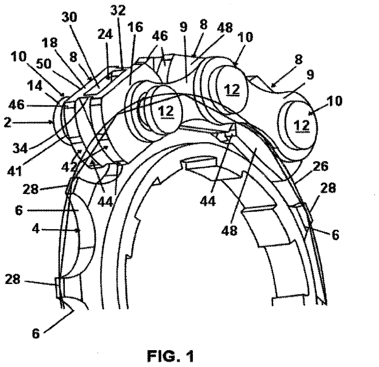
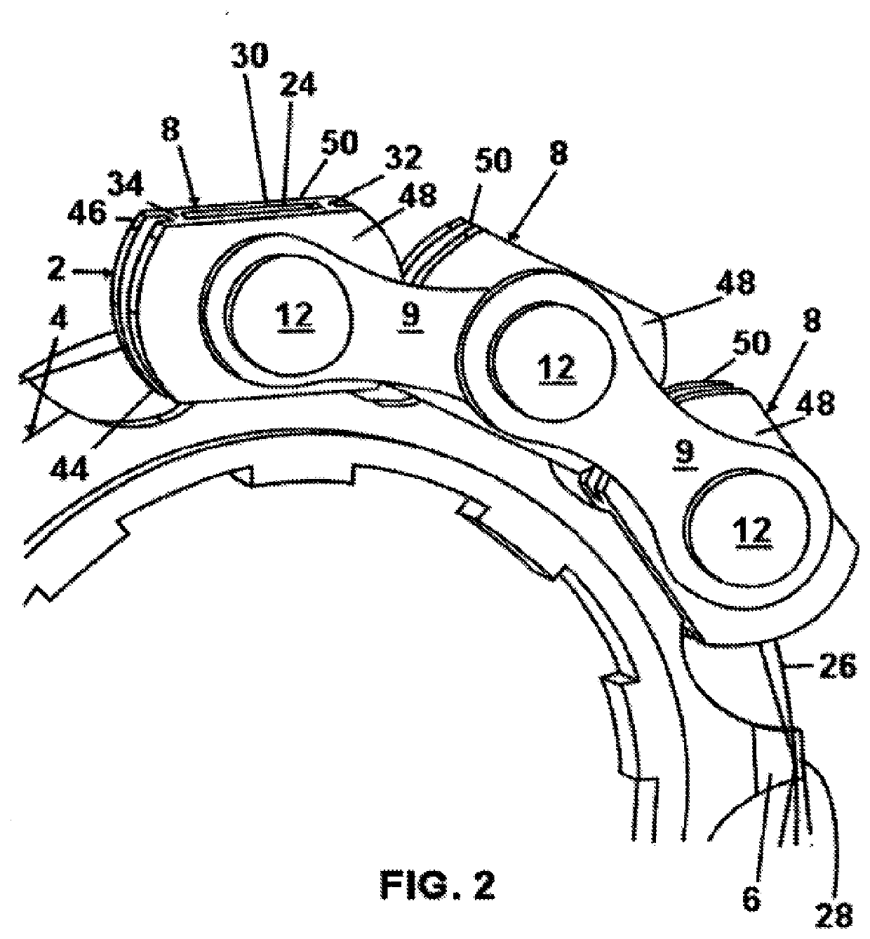
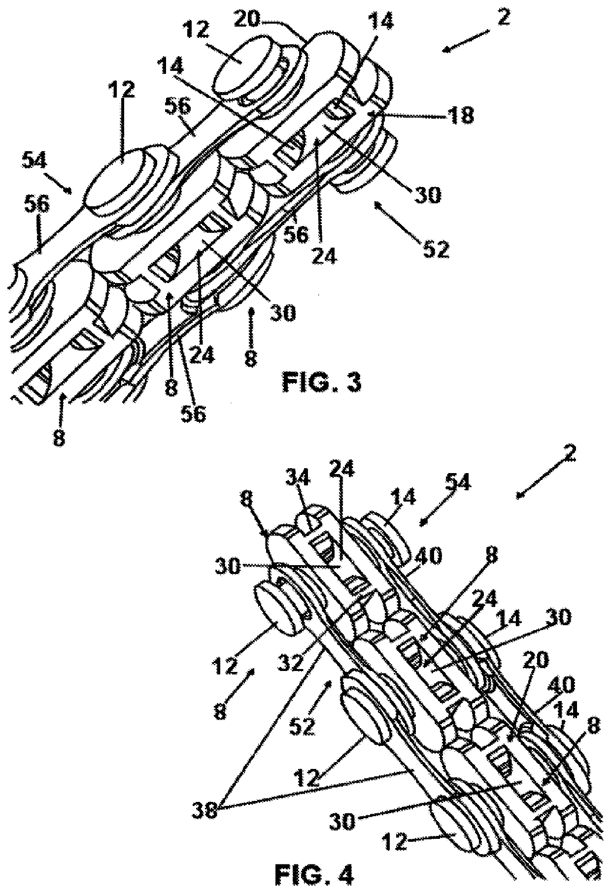
[0067]Referring to FIGS. 1-22, there is shown a power transmission chain 2 for use with a drive member 4 having a plurality of teeth 6. The power transmission chain 2 is that known as a roller chain and it may be used, for example, on bicycles, tricycles, motorcycles, chain saws and windmills.

[0068]The power transmission chain 2 comprises a plurality of chain links 8 which are pivotally connected together by connecting members 9 and pivot arrangements 10 so that the power transmission chain 2 can pass around the drive member 4 in use. Each one of the pivot arrangements 10 comprises a first pivot 12 and a second pivot 14. The first and second pivots 12, 14 extend towards each other from opposite sides 16, 18 respectively of the chain links 8. As best shown in FIGS. 7 and 8, the first and second pivots 12, 14 have adjacent ends 20, 22 respectively which face each other and which are spaced apart and thereby define a gap.

[0069]The power transmission chain 2 comprises a plurality of eng...


PUM


Abstract

A power transmission chain (2) for use with a drive member (4) having a plurality of teeth (6), and wherein: (i) the power transmission chain (2) comprises a plurality of chain links (8) which are pivotally connected together by connecting members (9) and pivot arrangements (10) so that the power transmission chain (2) can pass around the drive member (4) in use; (ii) each one of the pivot arrangements (10) comprises first and second pivots (12, 14) which extend towards each other from opposite sides (16, 18) of the chain links (8); (iii) the first and second pivots (12, 14) have adjacent ends (20, 22) which face each other and which are spaced apart; (iv) the power transmission chain (2) comprises a plurality of engaging formations (24) for enabling engagement with the drive member (4); (v) the engaging formations (24) are positioned between the adjacent ends (20, 22) of the first and second pivots (12, 14); and the engaging formations (24) and the spacing apart of the adjacent ends (20, 22) of the first and second pivots (12, 14) cause the power transmission chain (2) in use always to be positioned on the drive member (4) for maximum efficiency of drive transfer between the drive member (4) and the power transmission chain (2), and irrespective of the diameter of the drive member (4).

Description

CROSS-REFERENCE TO RELATED APPLICATIONS[0001]The present application is a continuation application of U.S. patent application Ser. No. 16 / 629,918, filed Jan. 9, 2020, which is a national stage application of International Application No. PCT / GB2018 / 000105, filed Jul. 10, 2018, which claims priority to Great Britain Application No. 1711342.4, filed Jul. 13, 2017, Great Britain Application No. 1715782.7, filed Sep. 28, 2017, and Great Britain Application No. 1717436.8, filed Oct. 24, 2017, the disclosures of all of which are incorporated herein by reference in their entirety, including any figures, tables, and drawings.FIELD OF THE INVENTION[0002]This invention relates to a power transmission chain and, more especially, this invention relates to a power transmission chain which is for use with a drive member having a plurality of teeth.BACKGROUND OF THE INVENTION[0003]Power transmission chains which are for use with a drive member having a plurality of teeth are well known.[0004]A fir...

Claims


Application Information

Patent Timeline
Patent Type & Authority Applications(United States)
IPC IPC(8): F16G13/06
CPCF16G13/06B62M9/00F16H7/06F16H2007/185
Inventor FOWLER, MARCEL
Owner NEW MOTION LABS LTD
Learn More