
Device for measuring bodily fluid drainage amount

a technology for bodily fluids and measuring devices, which is applied in the field of measuring devices for can solve the problems of inconvenient operation of measuring accurate urine drainage amounts, difficult to get a sound sleep, and medical staffs performing operations that cannot be performed, so as to reduce the work intensity of medical staffs related to the operation of measuring bodily fluid drainage amounts, the effect of convenient installation and use of devices

Pending Publication Date: 2022-11-10
KOREA UNIV RES & BUSINESS FOUND
View PDF0 Cites 1 Cited by
  • Summary
  • Abstract
  • Description
  • Claims
  • Application Information

AI Technical Summary

Benefits of technology

This patent is about a device that collects and measures bodily fluids. The device is made of a rigid material and has multiple sensors distributed in it. This allows the device to calculate and inform the same bodily fluid drainage amount even if it is tilted in various angles based on the patient's posture. This means that the patient can take any desired posture while the device is in use. The bodily fluid drainage amount can be automatically measured and discharged without requiring manual intervention, which reduces the workload of medical staffs. The device can also be conveniently installed and used with IoT communication technology, and the measurement results can be provided to external devices such as medical staff terminals, guardian terminals, and medical institution servers.

Problems solved by technology

If the two amounts of water do not match each other, the medical staff does not perform the operation.
This operation occupies a significant portion of the nurse's work and may be inaccurate if a measurement time is not properly observed, and for the patient, it may be difficult to get a sound sleep due to the nurse's treatment every hour.
In addition, since the urine collector 2 is formed of a vinyl material with a scale drawn thereon, it is inconvenient to perform an operation of measuring an accurate urine drainage amount only after the urine collector 2 is erected in a vertical direction.

Method used


Image

  • Device for measuring bodily fluid drainage amount
  • Device for measuring bodily fluid drainage amount
  • Device for measuring bodily fluid drainage amount

Examples


first embodiment

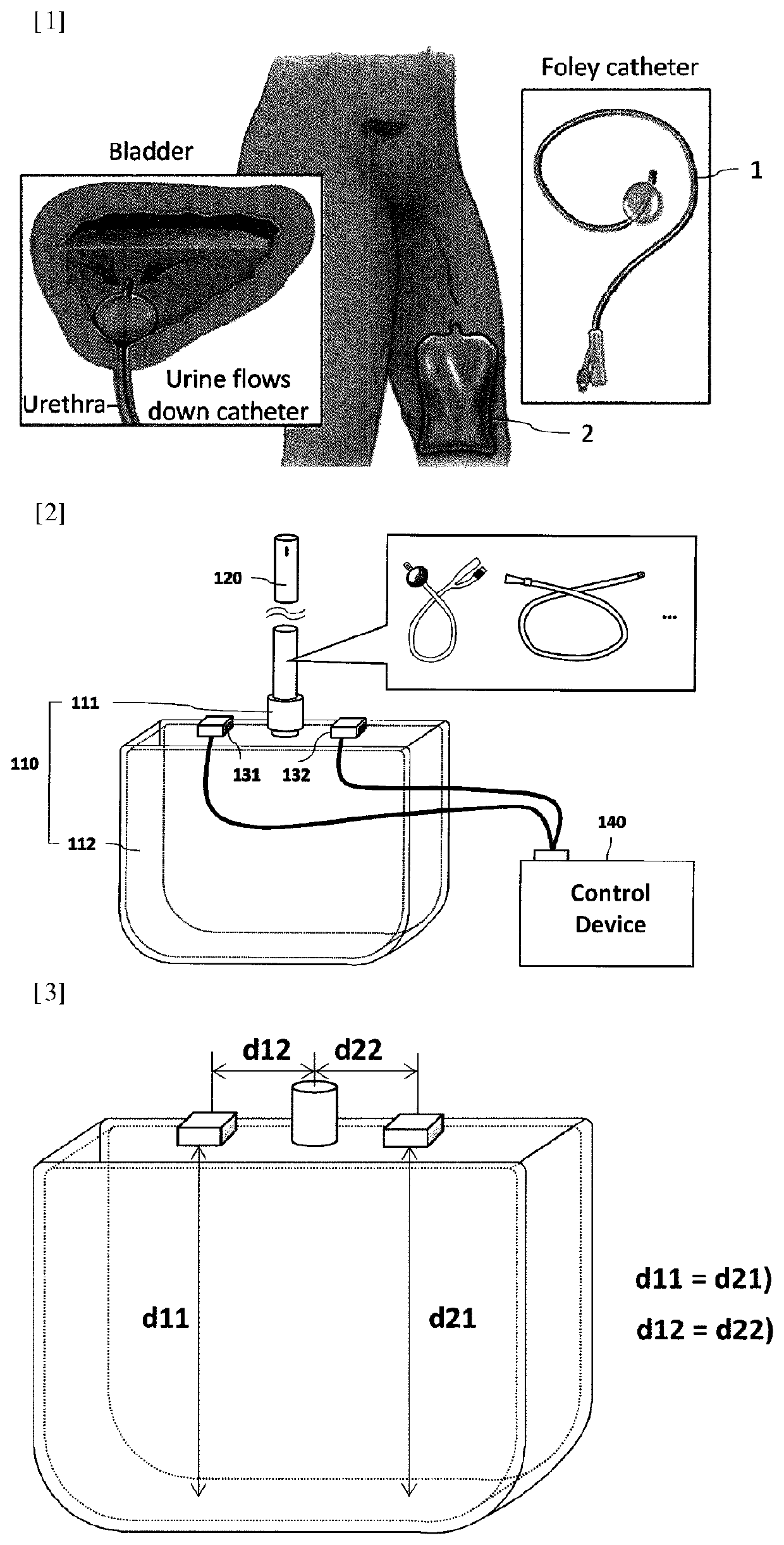
[0034]FIG. 2 is a diagram for describing a device for measuring a bodily fluid drainage amount according to the present disclosure.

[0035]Referring to FIG. 2, a device 100 for measuring a bodily fluid drainage amount of the present disclosure is configured by including a measurement case 110, a drainage tube 120, a plurality of fluid level sensors 131 and 132, a control device 140, and the like.

[0036]The measurement case 110 is formed of a rigid material to maintain a predetermined shape. In addition, a bodily fluid measurement space 111 provided therein and an entrance 112 connected with a bodily fluid collection space are provided.

[0037]The drainage tube 120 is coupled to the entrance of the measurement case in a releasable structure, and transfers bodily fluids discharged from a human body to the bodily fluid measurement space 111 of the measurement case 110.

[0038]For reference, the present disclosure may measure drainage amounts of all bodily fluids in the human body, such as gas...

second embodiment

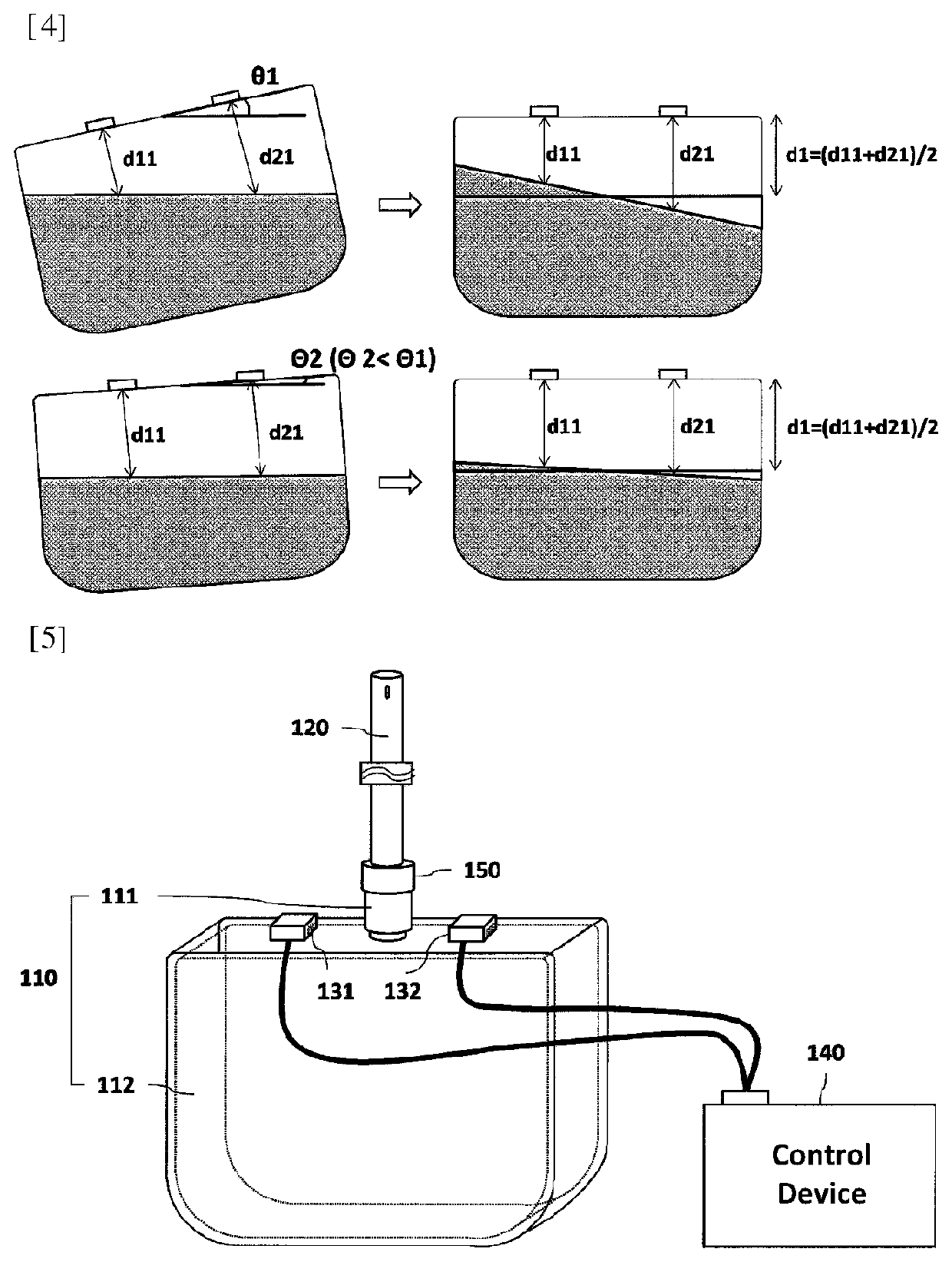
[0047]FIG. 5 is a diagram for describing a device for measuring a bodily fluid drainage amount according to the present disclosure.

[0048]Referring to FIG. 5, the device 100 for measuring the bodily fluid drainage amount of the present disclosure further includes an entrance valve 150 for closing or opening the entrance of the measurement case, in addition to the measurement case 110, the drainage tube 120, the plurality of fluid level sensors 131 and 132, and the control device 140.

[0049]In addition, the control device 140 activates operatively the plurality of fluid level sensors 131 and 132 at a predetermined period (e.g., 1 hour, 8 hours, and 24 hours) to perform the operation of measuring the fluid levels of the bodily fluids. In addition, while the operation of measuring the fluid levels of the bodily fluids is performed, the entrance of the measurement case is closed through the entrance valve 150 to temporarily block the inflow of a new bodily fluid.

third embodiment

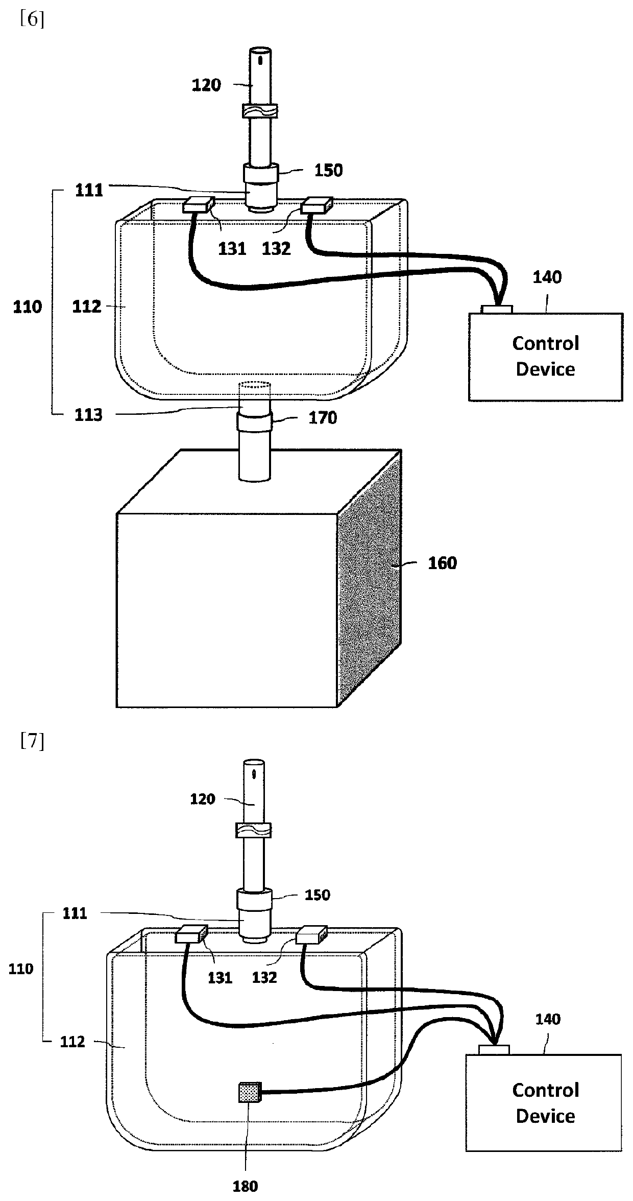
[0050]FIG. 6 is a diagram for describing a device for measuring a bodily fluid drainage amount according to the present disclosure.

[0051]Referring to FIG. 5, the measurement case 110 of the present disclosure may further include an exit 113 as well as the entrance 111.

[0052]In addition, in addition to the drainage tube 120, the plurality of fluid level sensors 131 and 132, the control device 140, and the entrance valve 150, the device may further include a collection container 160 which is coupled to the exit 113 of the measurement case 110 in a releasable structure to temporarily collect the bodily fluids discharged through the exit of the measurement case, and an exit valve 170 of opening the exit 113 of the measurement case 110 at a predetermined period under a control of the control device 140.

[0053]In addition, the control device 140 closes the entrance valve 150 while discharging the bodily fluids collected in the measurement case 110, thereby preventing a possibility to disch...


PUM


Abstract

The present invention relates to a device for measuring a bodily fluid drainage amount, the device comprising: a measurement case which is formed of a rigid material and provided with a bodily fluid measurement space therein; a drainage tube which is coupled to an entrance of the measurement case in a releasable structure and transfers bodily fluids discharged from a human body to the bodily fluid measurement space of the measurement case; a plurality of fluid level sensors, which are horizontally disposed on an upper surface of the measurement case and measure and inform fluid levels of the bodily fluids collected in the bodily fluid measurement space; and a control device which receives and analyzes the fluid levels of the bodily fluids, infers a tilt of the measurement case from a difference in the fluid levels of the bodily fluids, and calculates and informs a bodily fluid drainage amount.

Description

TECHNICAL FIELD[0001]The following description relates to a device for measuring a bodily fluid drainage amount, and more particularly, to a device for measuring a bodily fluid drainage amount so as to automatically, more easily and accurately measure the bodily fluid drainage amount.BACKGROUND ART[0002]The body fluid amount of a patient needs to be monitored in an operating room, medically ill / surgical intensive care units, and before and after major surgical operation, which may require prolonged anesthesia or may cause a hemodynamic instable situation.[0003]For example, after instructing the patient to fast before the operation, a medical staff compares the total amount of water injected into the patient with the amount of water excreted in the urine to perform the operation when the two amounts of water match each other. If the two amounts of water do not match each other, the medical staff does not perform the operation.[0004]Accordingly, in the related art, as illustrated in F...

Claims


Application Information

Patent Timeline
Patent Type & Authority Applications(United States)
IPC IPC(8): A61B5/20
CPCA61B5/20A61M2205/3389A61M2205/3576A61M1/00A61B5/208A61B5/201A61B5/1032A61B5/1121A61B5/746A61B5/7275A61B5/747A61M1/69A61M1/631A61M1/777A61M1/73A61M2205/3303A61M2205/3306
Inventor HONG, KWANG DAESONG, SEUNG JOONJUNG, SANG HOONKIM, JAE YOUNG
Owner KOREA UNIV RES & BUSINESS FOUND
Learn More