Vehicle

a technology for vehicles and vehicles, applied in the field of vehicles, can solve the problems of imposing drag penalties, affecting the visual appearance of vehicles, and requiring a high level of lateral acceleration, and achieve the effect of not exceeding the battery capacity

Pending Publication Date: 2022-11-10
GORDON MURRAY AUTOMOTIVE LTD
View PDF0 Cites 3 Cited by
  • Summary
  • Abstract
  • Description
  • Claims
  • Application Information

AI Technical Summary

Benefits of technology

[0013]The at least one aperture on the upper surface is preferably located to the rear of the upper surface, in order to provide the desired control of the boundary layer. Likewise, the at least one aperture on the under surface is preferably located towards the rear of the under surface, ideally at a longitudinal position on the vehicle that is substantially aligned with the centre of pressure of the vehicle. The under surface can include a step formation, ahead of which the underside is relatively lower and behind which the underside is relatively higher, and the at least one aperture on the under surface is then preferably located to the rear of the step formation. Generally, the use of the present invention means that the design of the under surface can be less constrained by the needs of ground effect thus allowing other influences to be taken into account to a greater degree.
[0014]Given that the fan is present, it can be used for other purposes in addition. For example, further ducting can be provided leading from the engine compartment of the vehicle, and the control unit adapted to cause the fan to draw air through that ducting when certain criteria are met, such as the vehicle speed being below a (further) preset speed, or the engine bay temperature being above a preset limit. Essentially, while the vehicle is at rest or at a low speed, the fan can be used to purge hot air from the engine compartment and thus protect the structure of the vehicle and its power train from excessive temperatures.
[0015]Although other drive arrangements for the fan are possible, it is preferably electrically powered as this is likely to be the most convenient. Normally, this would imply that power is provided from the vehicle generator, i.e. driven by the engine. We prefer, however, that the fan can selectably receive electrical power from the generator or from an on-board battery, and that the control unit is adapted to provide power to the fan from the generator when the vehicle speed is below a preset speed, and permit power to be provided to the fan from the battery when the vehicle speed is above that preset speed. Thus, when the vehicle is at or near its Vmax, the engine power that would be needed to drive the generator and provide power for the fan can be provided from the battery instead. Typically, such vehicles spend only a brief period at Vmax so the battery capacity need not be excessive. A control (such as a switch) can be provided, actuatable by a driver within the car, and the control unit adapted to provide power to the fan from the battery when both the vehicle speed is above the preset speed and the control is actuated.

Problems solved by technology

However, these are often seen as contradictory; high cornering performance requires a high level of lateral acceleration, which is provided via the grip produced by the tyres.
This is straightforward to do, by providing wings and other aerodynamic devices, but these impose a drag penalty and can dominate the visual appearance of the vehicle.
Thus, the higher level of downforce needed to produce sufficient grip to achieve high-speed cornering performance brings with it a level of drag that reduces the straight-line top speed performance of the vehicle and impacts vehicle efficiency.
Generally, to escape that trade-off requires that the drag effect of the aerodynamic devices must be overcome by a higher-power engine, which inevitably imposes a weight penalty on the vehicle.
As a result, the BT46B was notably faster, with the principal limitation in its cornering performance being the ability of the driver to cope with the lateral acceleration that was produced.
This is obviously impractical on a road car, so other approaches have been taken in recently-designed hypercars.
However, the driver must complete a checklist to confirm that they understand that the handling of the vehicle will be impaired.
As a result, the process is inflexible and (deliberately) inconvenient.

Method used


Image

  • Vehicle
  • Vehicle
  • Vehicle

Examples


Embodiment Construction

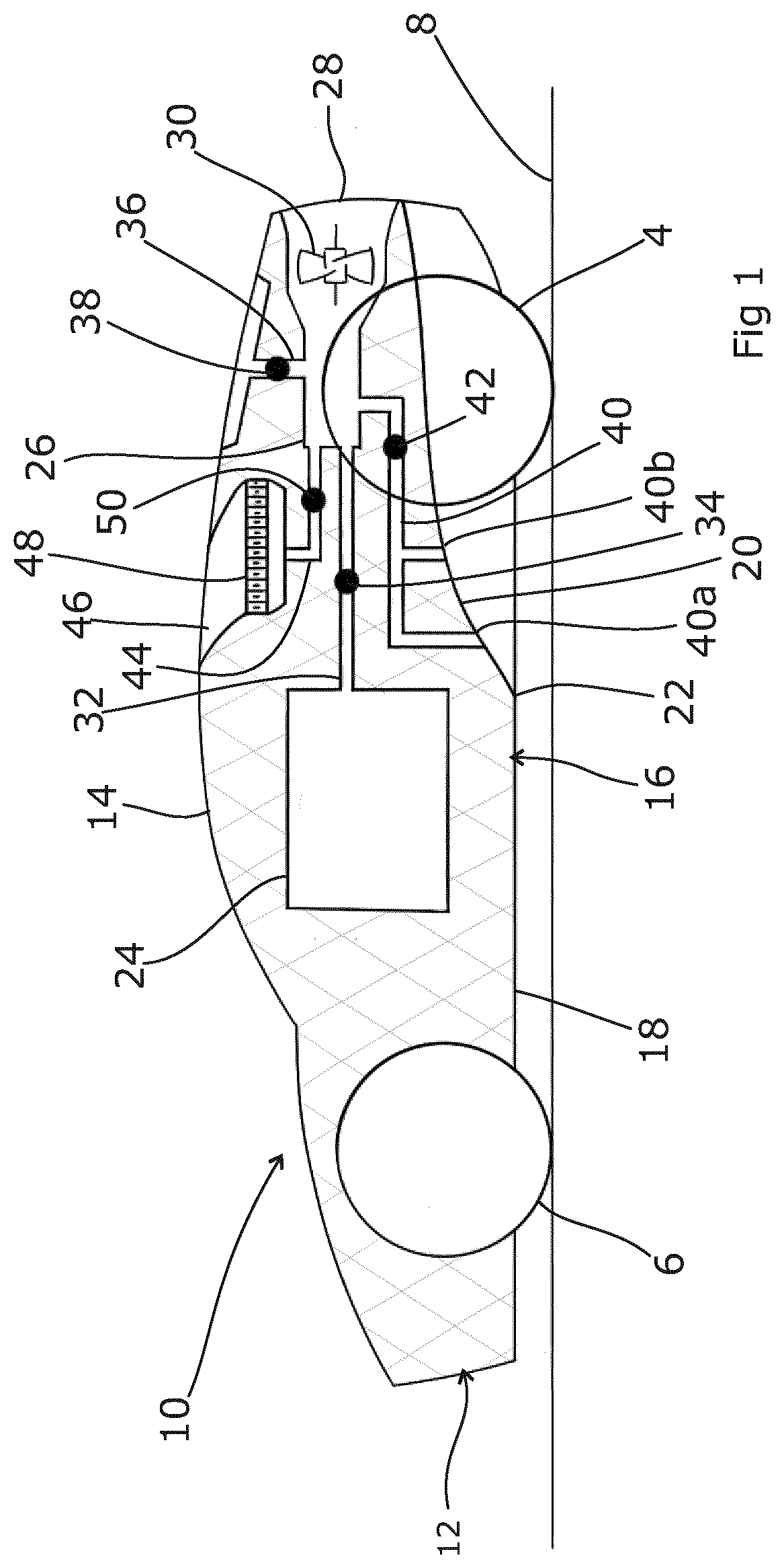
[0027]FIG. 1 shows a vehicle embodying the present invention, in the form of a car 10 resting on the ground 8 via front and rear wheels 6, 4, which are attached to the car 10 via a suspension arrangement (not shown). The car 10 is shown in schematic form only for clarity; thus the illustration shows a bodyshell 12 comprising an upper body surface 14 and an under-surface 16 that itself consists of a forward undertray 18 and a rearwardly-located diffuser 20. The forward undertray 18 is generally flat, level and smooth in order to allow for a smooth airflow under the car. In some cases, although not illustrated, there may be a leading edge. At a point part way along the underside of the car 10 it transitions at a step 22 to the diffuser 20. The diffuser 20 defines an under-surface to the car 10 which arches upwardly to provide a greater spacing between the under-surface 16 and the ground 8 beneath the rear section of the car 10.

[0028]It should be understood that this configuration of t...


PUM


Abstract

A vehicle has external bodywork including an upper surface and an under surface, the under surface having at least one aperture, and the vehicle comprising lower ducting located within the external bodywork and communicating with that aperture, the upper surface having at least one aperture, and the vehicle comprising upper ducting located within the external bodywork and communicating with that aperture, the upper ducting and the lower ducting leading to a fan adapted to selectively draw air through the respective ductings, the vehicle further comprising a control unit adapted to receive information as to the vehicle dynamic state and, in the light of that state, draw air through the lower ducting or through the upper ducting. Thus, a choice can be made between enhanced levels of downforce on the one hand, and low drag on the other. By providing pre-set thresholds for parameters such as speed, g-force, vehicle attitude or the like within the control unit, the car can be tailored so that it is optimised for low drag during high speed straight-line driving, when tight cornering is unlikely, and optimised for greater downforce when lateral grip is more likely to be needed.

Description

FIELD OF THE INVENTION[0001]The present invention relates to a vehicle.BACKGROUND ART[0002]The two fundamental requirements of a vehicle are that it be able to move forward and change velocity. A sports car seeks to maximise both capabilities, by permitting a high rate of acceleration to a high top speed, exceptional braking power and stability, and allowing good cornering ability even at all road speeds. However, these are often seen as contradictory; high cornering performance requires a high level of lateral acceleration, which is provided via the grip produced by the tyres. This is the result of downforce exerted on the tyres by the vehicle weight and aerodynamics, and as the weight should be minimised (for numerous reasons) that means the downforce needs to be produced aerodynamically. This is straightforward to do, by providing wings and other aerodynamic devices, but these impose a drag penalty and can dominate the visual appearance of the vehicle.[0003]Thus, the higher level...

Claims


Application Information

Patent Timeline
Patent Type & Authority Applications(United States)
IPC IPC(8): B62D35/00B62D37/02
CPCB62D35/00B62D37/02
Inventor MURRAY, IAN GORDON
Owner GORDON MURRAY AUTOMOTIVE LTD
Why Eureka
Try Eureka