Electronic equipment

Pending Publication Date: 2022-11-17
SONY SEMICON SOLUTIONS CORP
View PDF0 Cites 1 Cited by
  • Summary
  • Abstract
  • Description
  • Claims
  • Application Information

AI Technical Summary

Benefits of technology

The technical effects of this patent text are to prevent degradation of the image quality of captured images and the display quality of the display section. This is achieved by controlling the display section to not show images or to display them less frequently, especially when the imaging section is in use. Additionally, the patent proposes a method to make the display appear less discomfortable by reducing the pixel density of the display region that overlaps the camera module.

Problems solved by technology

On the other hand, a smaller-sized display screen reduces the size of characters displayed, which decreases with increasing display resolution, making the characters difficult to view.
Further, in a case where the camera is disposed on the bezel, for example, during a video chat, the gaze is often focused near the center of the display screen and is misaligned with the optical axis of the camera.
This leads to a captured image with a misaligned gaze, which brings a sense of discomfort.

Method used


Image

  • Electronic equipment
  • Electronic equipment
  • Electronic equipment

Examples


first embodiment

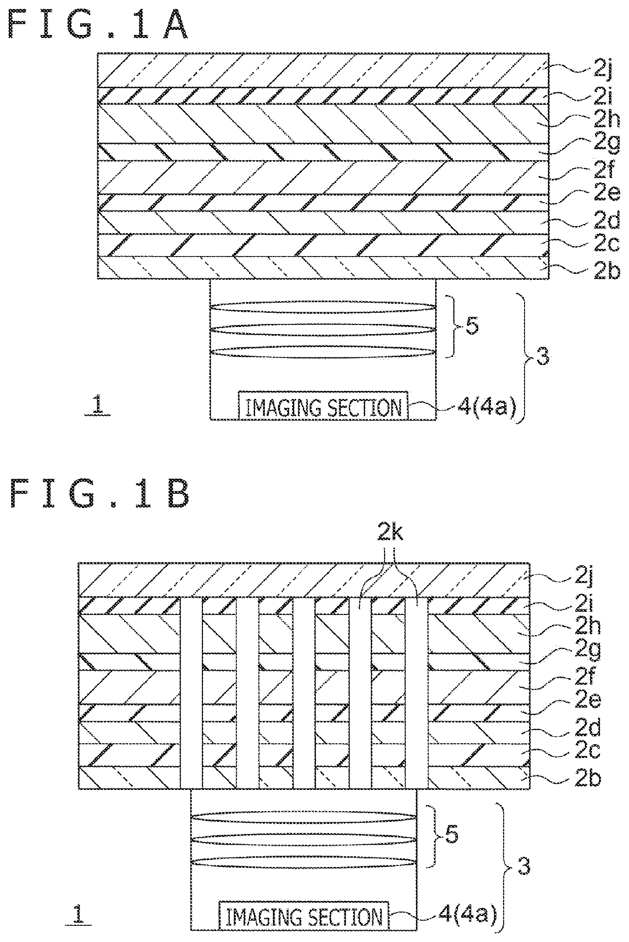
[0066]FIG. 1A and FIG. 1B are schematic cross-sectional views of electronic equipment 1 according to a first embodiment. The electronic equipment 1 in FIG. 1A is any electronic equipment 1 such as a smartphone, a cellular phone, a tablet, or a PC which includes both a display function and an image capturing function. The electronic equipment 1 in FIG. 1A includes a camera module (imaging section) disposed opposite to a display surface 1a of a display section 2. In such a manner, the electronic equipment 1 in FIG. 1A is provided with a camera module 3 on a rear side of the display surface 1a of the display section 2. Thus, the camera module 3 captures images through the display section 2.

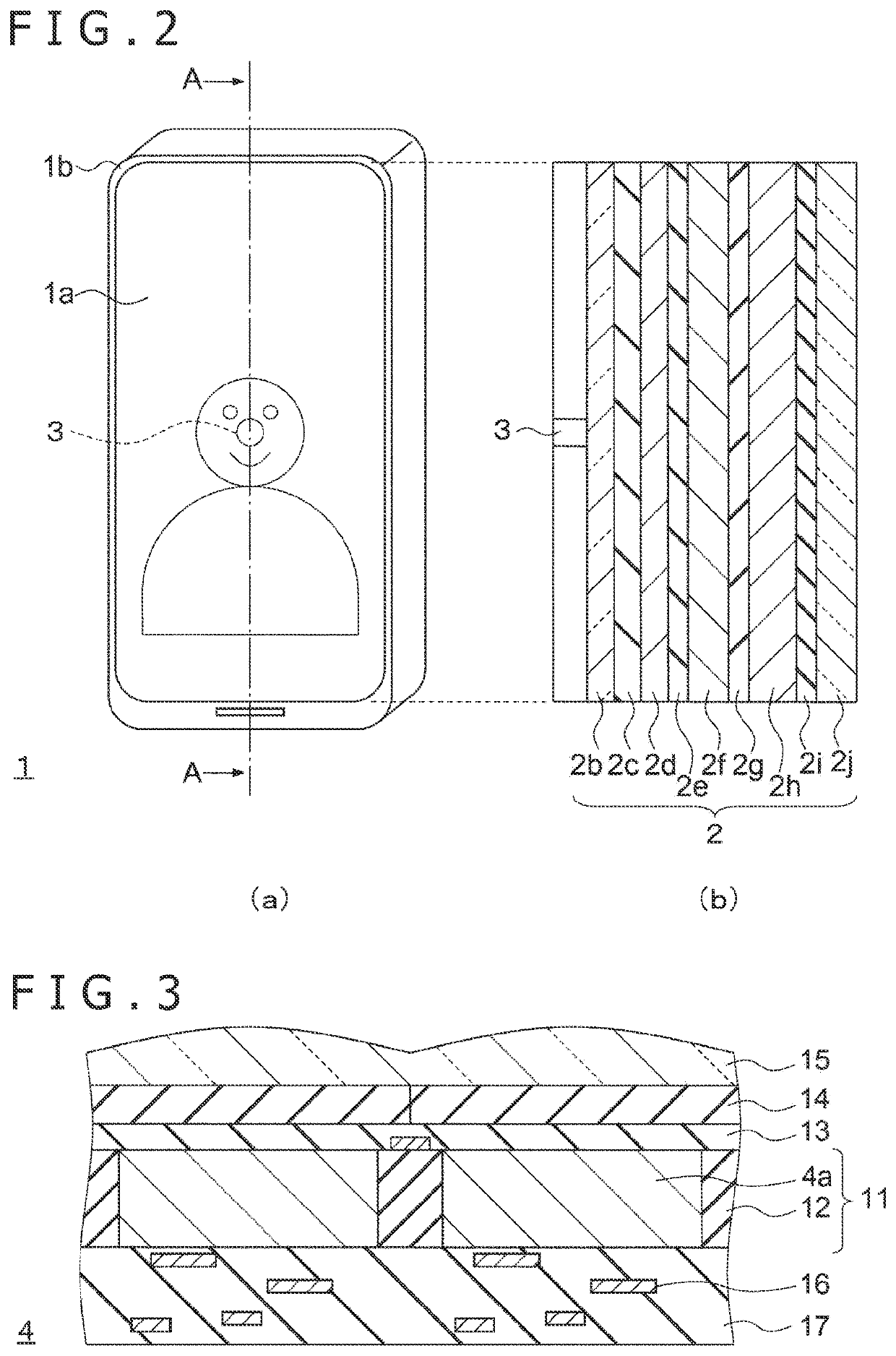
[0067]FIG. 2(a) is a schematic diagram of the appearance of the electronic equipment 1 in FIG. 1A, and FIG. 2(b) is a cross-sectional view of the electronic equipment 1 taken in the direction of line A-A in FIG. 2(a). In an example in FIG. 2(a), the display surface 1a approximately spans the external...

second embodiment

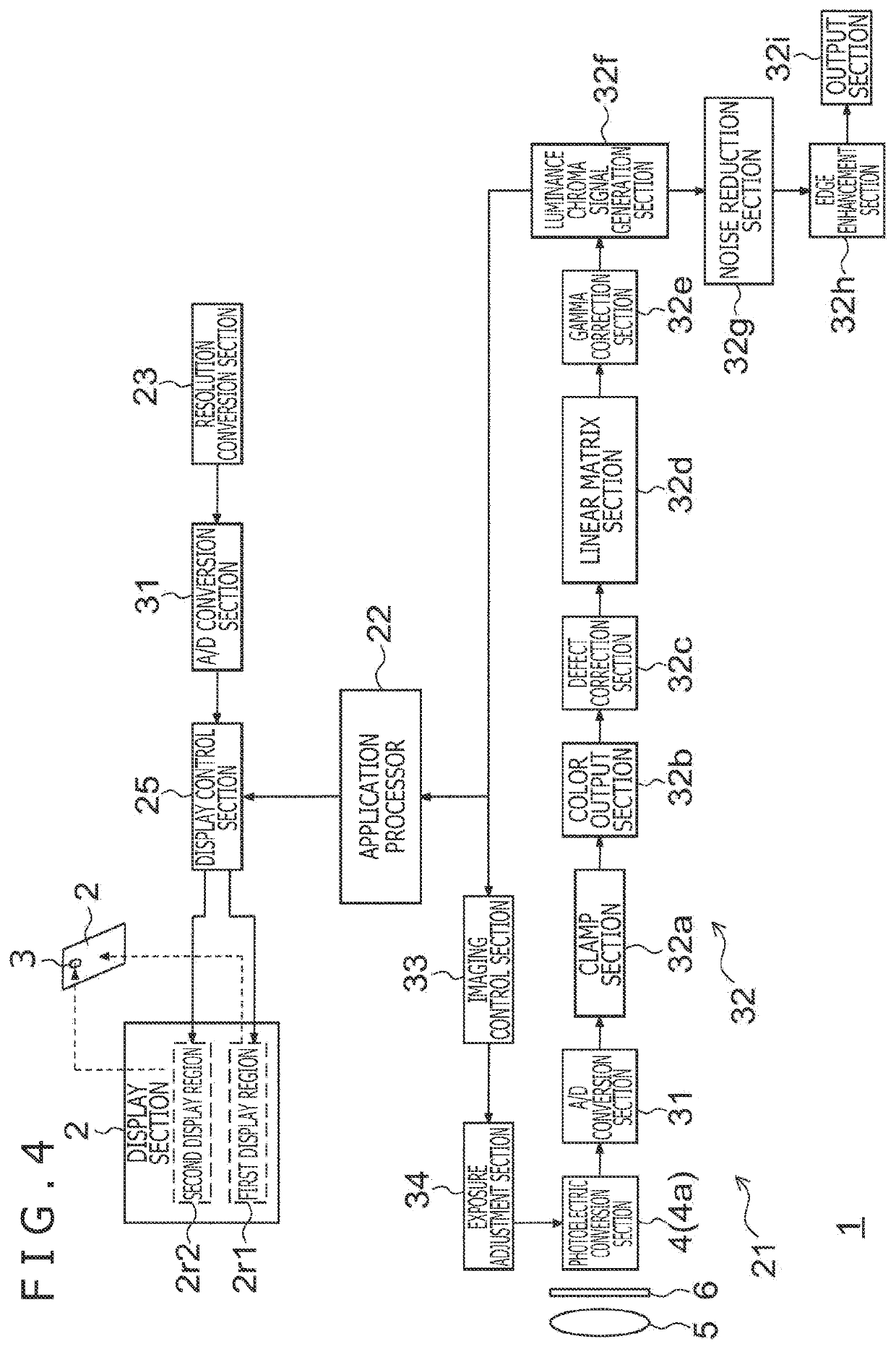
[0096]When the frame rate of the display section 2 is reduced during activation of the camera module 3 as in the first embodiment, human eyes perceive the display to be darker than the normal display because the eyes sense brightness according to an averaged luminance. Thus, in a second embodiment, the luminance value of pixel data is increased when the camera module 3 is activated.

[0097]The electronic equipment 1 according to the second embodiment has an internal configuration similar to that in FIG. 4. FIG. 7 is a flowchart depicting processing operations of the electronic equipment 1 according to the second embodiment. Differences from the flowchart in FIG. 5 will mainly be described below. In FIG. 7, in a case where the camera module 3 has not been activated (NO in step S11), around the time of performing processing for selecting the normal frame rate (step S12), a normal luminance value is set (step S13). The normal luminance value means performing display with the original lum...

third embodiment

[0103]A third embodiment not only reduces the frame rate but also controls the display pixel density when the camera module 3 is activated. The electronic equipment 1 according to the third embodiment has an internal configuration similar to that in FIG. 4.

[0104]FIG. 9 is a flowchart depicting processing operations of the electronic equipment 1 according to the third embodiment. Differences from FIG. 7 will mainly be described below. Processing in steps S21 to S24 is similar to that in steps S11 to S14 in FIG. 7.

[0105]In a case where the camera module 3 is activated, the frame rate and the display pixel density are set (step S25). In this regard, the low frame rate, which is lower than the normal frame rate, is set. Further, for the display pixel density, set is a display pixel density that is lower than the display pixel density set in a case where the camera module 3 is not activated. As a more specific example, in a case where the camera module 3 is activated, every other horizon...


PUM


Abstract

[Object] Provided is electronic equipment that prevents degradation of image quality of captured images and display quality of a display section.[Solving Means] The electronic equipment includes a display section, an imaging section disposed opposite to a display surface of the display section, and a control section that synchronizes a display timing of the display section with an imaging timing of the imaging section such that the imaging section performs imaging at a timing when the display section does not perform displaying.

Description

TECHNICAL FIELD[0001]The present disclosure relates to electronic equipment.BACKGROUND ART[0002]In recent electronic equipment such as smartphones, cellular phones, and PCs (Personal Computers), a camera is mounted on a bezel of a display section to easily allow a video chat or video shooting. A smartphone or a cellular phone is often carried in a pocket or a bag, and thus needs to have as compact an external size as possible. On the other hand, a smaller-sized display screen reduces the size of characters displayed, which decreases with increasing display resolution, making the characters difficult to view. Hence, studies have been conducted for reducing the width of the bezel, located at the periphery of the display screen, to make the size of the display screen as large as possible without increasing the external size of the electronic equipment.[0003]However, a camera or the like is often mounted on the bezel of the electronic equipment, preventing the bezel width from being mad...

Claims


Application Information

Patent Timeline
IPC IPC(8): H04N5/232H04N5/04
CPCH04N5/23293H04N5/04H04N5/23245G03B29/00H04N23/667H04N23/63H04N23/71H04N23/73G09G5/10H04N7/144G09G2340/0435G09G2360/144G09G2320/0653G09G2310/06G09G2320/0686G03B30/00H04N23/57G09G5/391H04N7/14H04N5/06
Inventor KANAI, JUNICHINAKATA, MASASHI
Owner SONY SEMICON SOLUTIONS CORP
Why Eureka
Try Eureka