Unlock instant, AI-driven research and patent intelligence for your innovation.

Servo-motor driving method

Inactive Publication Date: 2000-01-04
TAMAGAWA SEIKI CO LTD
View PDF4 Cites 1 Cited by
  • Summary
  • Abstract
  • Description
  • Claims
  • Application Information

AI Technical Summary

Benefits of technology

The present invention has been realized in order to solve the above problems and particularly aims to provide a method for driving a servo-motor wherein, by detecting power voltage without using a conventional current feedback loop for motor current detection and controlling current using this detected value, control properties can be improved and cost lowered, and in addition, control performance can be improved when motor temperature has increased.

Problems solved by technology

Since the conventional servo-motor driving method has the configuration described above, it has problems such as the following.
That is, a current sensor and an expensive A / D converter are required in order to form the current feedback system, constituting a considerable obstacle to lowering the cost of the control system.

Method used


Image

  • Servo-motor driving method
  • Servo-motor driving method
  • Servo-motor driving method

Examples


Embodiment Construction

There will be detailed below the preferred embodiment of the servo-motor driving method of the present invention with reference to the accompanying drawings. Like and similar members to the conventional example are explained using like reference characters.

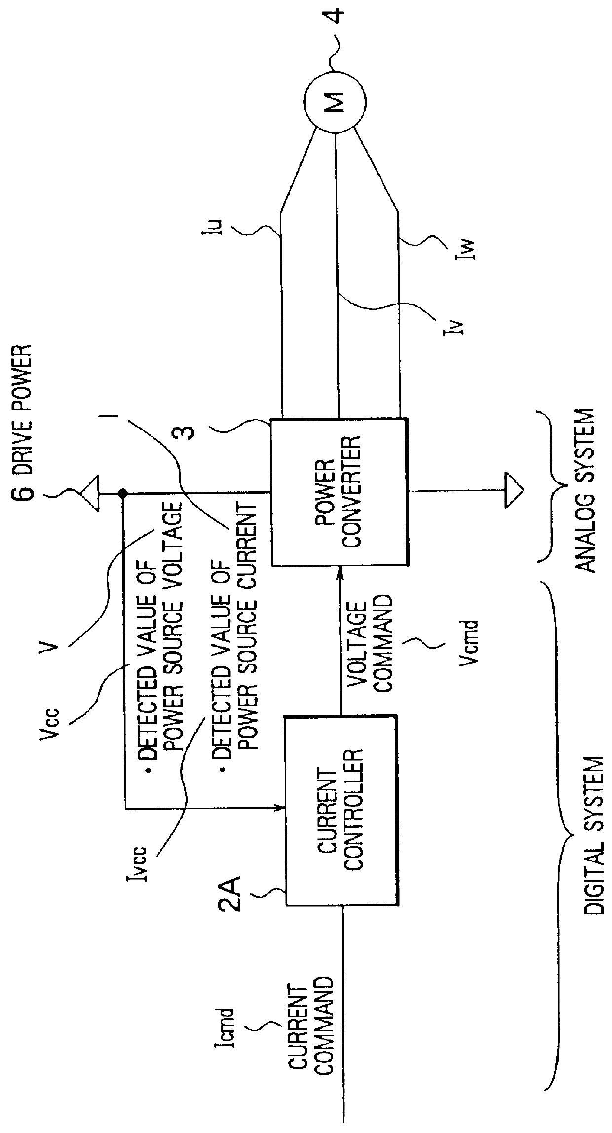
As shown in FIG. 2, current command Icmd, which comprises a current command value, is input to a current controller 2A and a voltage command Vcmd from the current controller 2A is applied to a known power converter 3. A drive power source 6, for driving power elements not shown in the diagram, is connected to the power converter 3. The power converter 3 supplies a three-phase drive current Iu, Iv, Iw to a servo-motor 4. Furthermore, a detected value Vcc of a power voltage V of the drive power source 6 and a detected value Ivcc of a power current I of the drive power source 6 are captured by the current controller 2A.

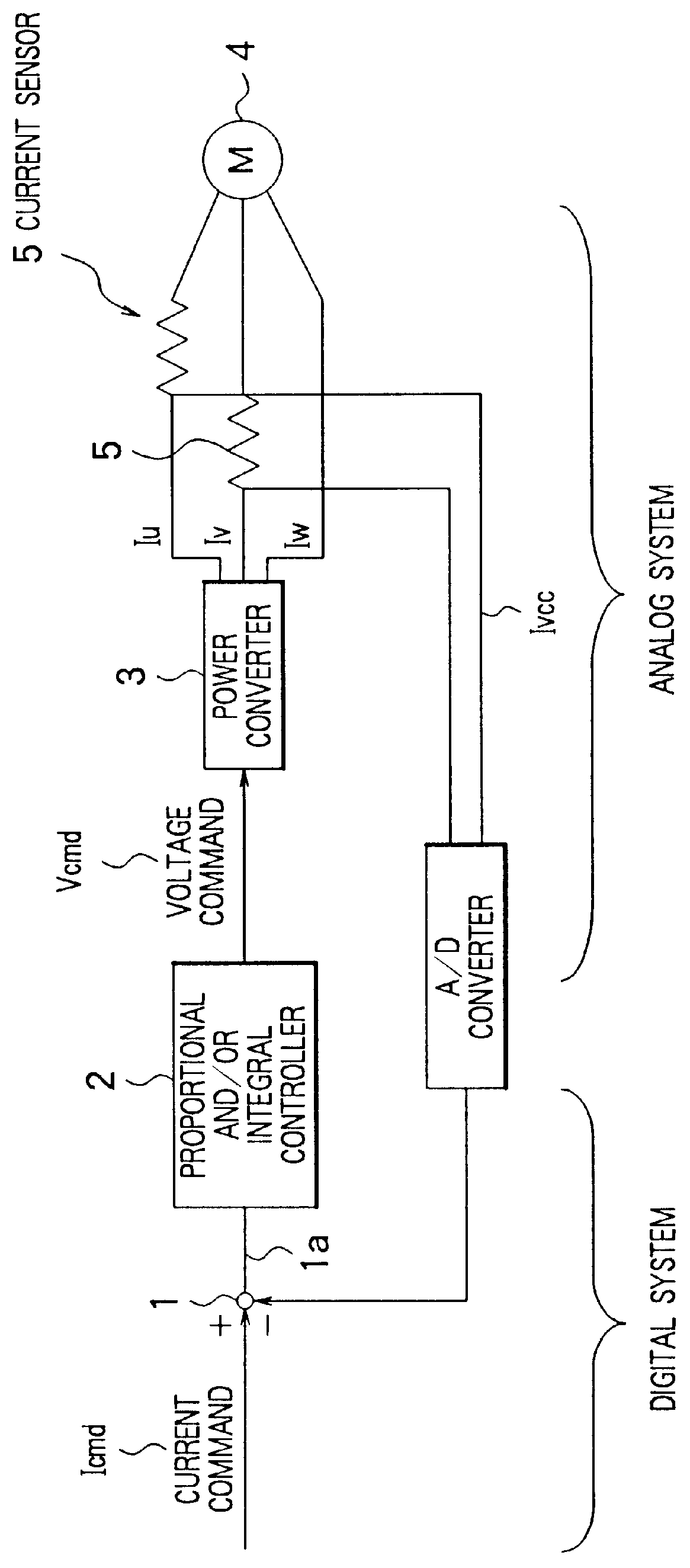
The control system shown in FIG. 2 differs from the conventional control system of FIG. 1 in respect of the fact tha...


PUM


Abstract

A conventional method for driving a servo-motor carried out control by means of a current feedback loop, using a current sensor and an A / D converter; therefore, the number of parts was great, cost reduction was difficult and it was difficult to avoid control errors caused by errors in the precision of the current sensor. A method for driving a servo-motor of the present invention comprises detecting a power voltage (V) of a servo-motor (4), controlling a voltage command (Vcmd) to a power converter (3) by numeric calculation using a detected value (Vcc) of this power voltage (V), and controlling power of a drive current (Iu, Iv, Iw).

Description

BACKGROUND OF THE INVENTION1. Field of the InventionThe present invention relates to a method for driving a servo-motor, and more particularly to a new improvement for detecting power voltage without using a current feedback loop, comprising a current sensor and an A / D converter, which is conventionally used for detecting motor current, and controlling current using this detected value, thereby improving control properties when motor temperature has increased and lowering cost.2. Description of the Related ArtFIG. 1 shows a conventional method of this type which has generally been used as a method for driving a servo-motor.That is, a current command Icmd is input to a calculator 1. The output 1a of the calculator 1 is sent via a proportional and / or integral controller 2 and is input as a voltage command 2a to a power converter 3, comprising a known power element configuration. The power converter 3 supplies a three-phase drive current Iu, Iv, Iw to a servo-motor 4. A current sensor ...

Claims


Application Information

Patent Timeline
IPC IPC(8): H02P5/00H02P29/00
CPCH02P29/00H02P5/00H02P23/14H02P29/60
Inventor YASUI, TAKAJI
Owner TAMAGAWA SEIKI CO LTD