Inflatable sole lining for shoes and boots

Inactive Publication Date: 2000-01-18
LAKIC NIKOLA
View PDF38 Cites 231 Cited by
  • Summary
  • Abstract
  • Description
  • Claims
  • Application Information

AI Technical Summary

Benefits of technology

It is still a further objective of this invention to provide a light weight, shock-absorbing resilient inner sole for footwear which enhances the stability and comfort of the footwear to the wearer.
It is yet anothe

Problems solved by technology

These inner soles have provided only limited shock absorbency, resulting in little or no significant improvement in wearer comfort.
While this is an attempt to increase wearer comfort, water is heavy, non-compressible and the inner sole cannot be adjusted for firmness, and cannot provide shock absorbency.
Additionally, water is unsuited for use in freezing climates.
Also, a leak will wet the inside of the bootwear, and this inner is not breathable.
Since it is impossible to preclude diffusion of gases through the plastic, the inflatable insert or inner sole is acknowledged to experience a rapid increase in pressure shortly after manufacture, f

Method used


Image

  • Inflatable sole lining for shoes and boots
  • Inflatable sole lining for shoes and boots
  • Inflatable sole lining for shoes and boots

Examples


Embodiment Construction

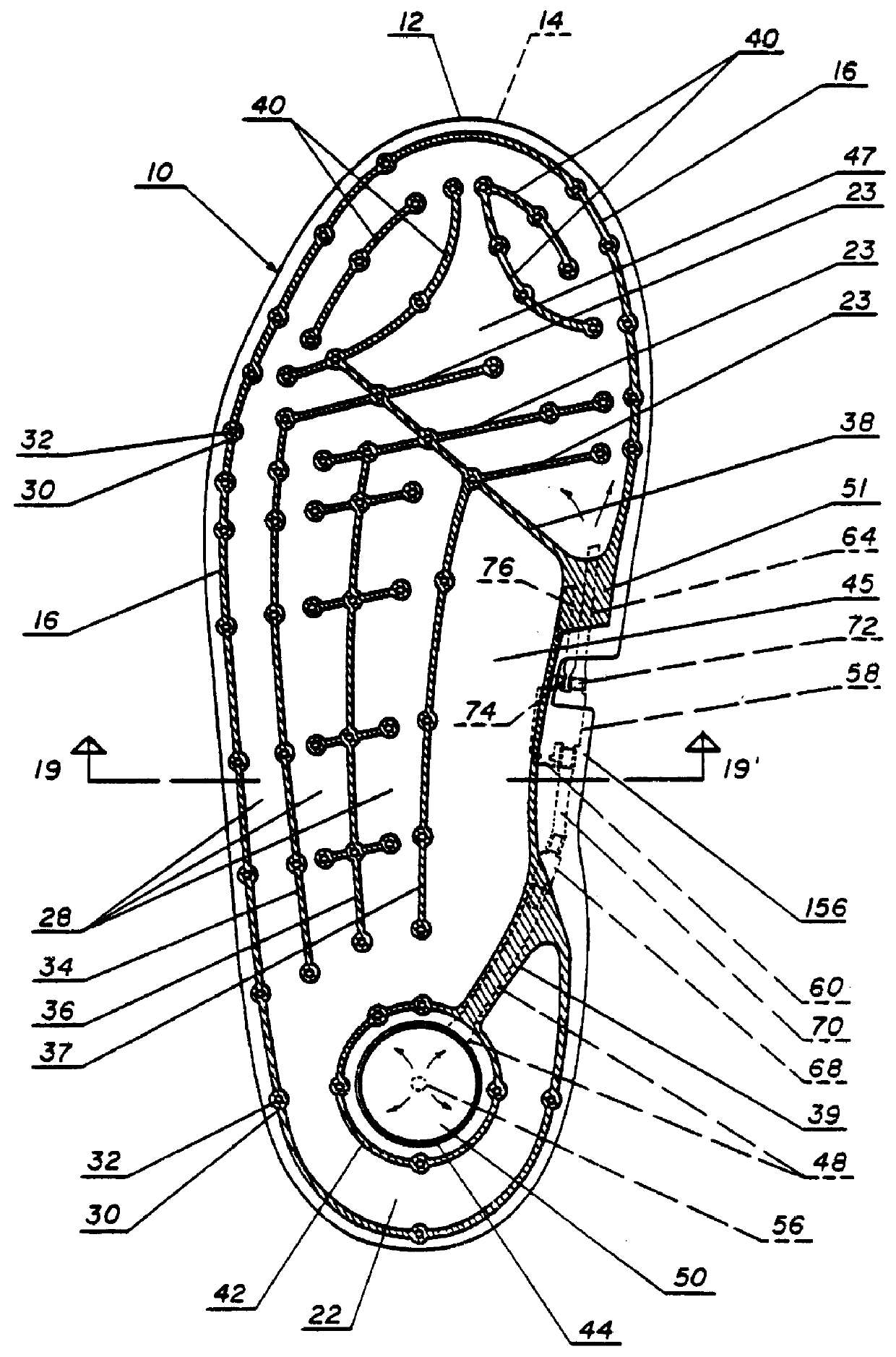
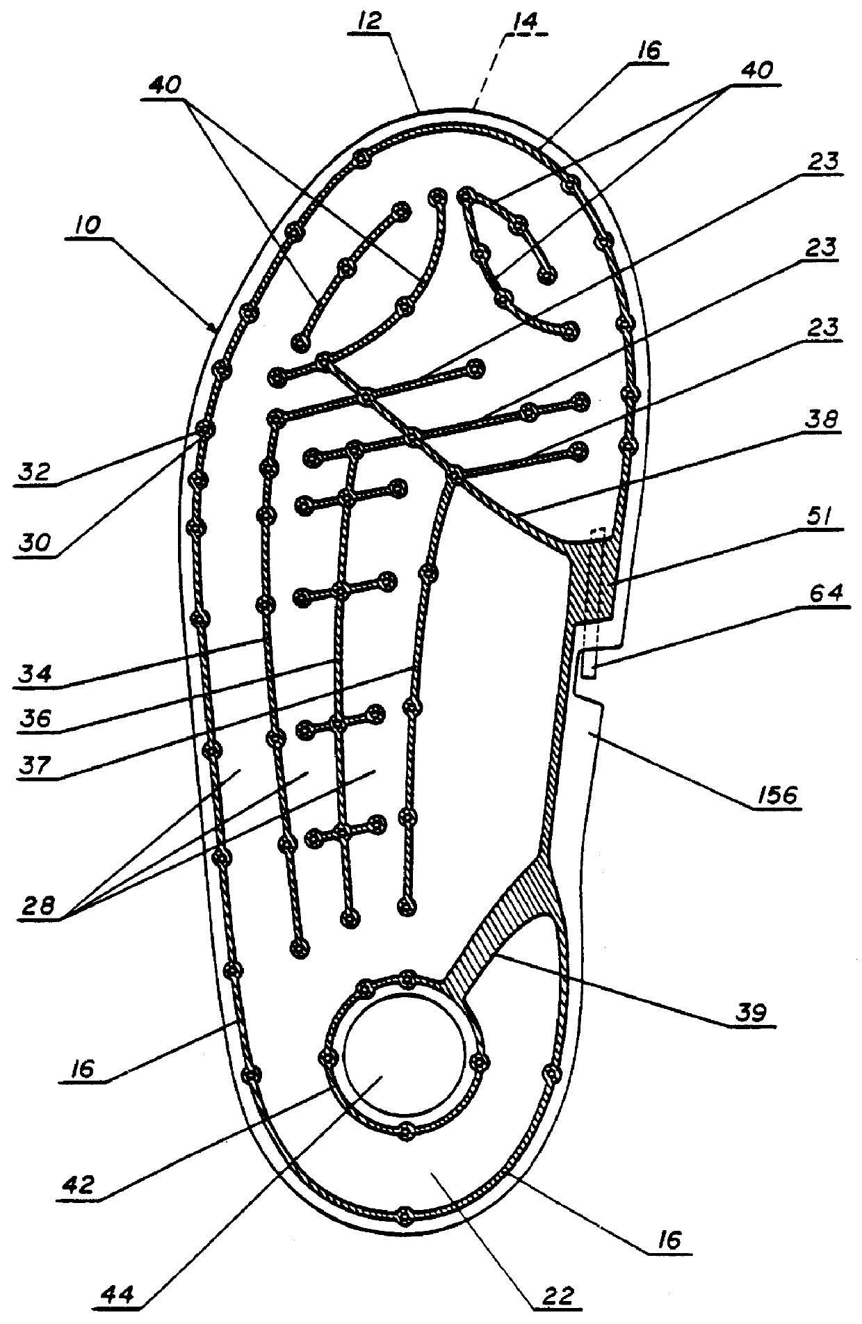
Referring now to FIG. 1, the inflatable insole 10 of the invention is shown in plan view. The inner sole 10 is formed by a first sheet 12 and a coextensive second sheet 14 of substantially the same shape and size. The first and second sheets 12 and 14 are bonded together in a continuous peripheral seam 16 that extends about the toe, the lateral side of the inner sole 10, the heel and medially about the instep. The seams are shown in the figures as cross hatched areas. This is intended to show seamed areas only and not to represent sectional views.

The first and second sheets 12 and 14 are preferably plastic and most preferably are thermoplastic, so that conventional heat sealing can be used for forming the seams. The most preferred thermoplastic material is polyurethane, however, other suitable materials include ethylene, and ethylene vinyl acetate copolymers, polyethylene, polypropylene, polyvinyl chloride, etc. Natural or synthetic rubber can also be used.

The first sheet 12 and sec...


PUM


Abstract

There is disclosed an inflatable lining for selected inner surfaces of footwear, such as a shoe, boot or sandal. The inflatable lining is formed of first and second plastic sheets having the shape and size of the selected inner surfaces, e.g., a sole, or any portion of the upper surfaces of the footwear. The sheets are bonded together in a continuous seam about their peripheral edges thereby forming a sealed interior chamber. A plurality of discontinuous seams are formed between the first and second sheets to create within the sealed interior chamber a plurality of interconnecting tubular passageways, and at least one continuous seam can also be provided that subdivides the interior chamber into two or more subdivided interior chambers. The inflatable liner is provided with an air pump that preferably is a flexible bulb with an inlet valve which discharges into a flexible tube which extends to a pressure control valve and then to the interior chamber of the inflatable inner sole. Preferably the flexible bulb is mounted at the heel of the inner sole. The pressure relief valve is manually adjustable to control the pressure within the inflatable inner sole. Excess air from the pressure control valve can be directed into channels formed on the undersurface of the inner sole where it discharges through sealed apertures in the inner sole thereby providing forced air circulation in the footwear. Alternatively, manually operated air pumps can be provided.

Description

1. Field of the InventionThis invention relates to an inflatable lining for shoes, boots and the like, and in particular, relates to an inflatable lining having a pump to pressurize the lining and to induce air circulation through the shoe, and with independent compartments within the lining which are provided with pressure control valves to control the pressure and, hence, the firmness, shock absorbency, stability, resiliency and comfort of each compartment of the lining.2. Brief Statement of the Prior ArtInner soles have been provided for shoes and boots which are formed of a compressible, elastic material such as cellular plastic foams, foam rubber, etc. These inner soles have provided only limited shock absorbency, resulting in little or no significant improvement in wearer comfort.Some prior investigators have provided inner soles with inflated cushions at either the toe and heel areas, and some have provide cushions at both areas with circulation between the two cushions. The ...

Claims


Application Information

Patent Timeline
IPC IPC(8): A41D13/00A41D19/015A43B13/18A43B13/20A43B17/03A43B17/00A43B5/04A43B23/16A43B23/00B29D31/50B29D31/515B29D35/12
CPCA41D19/01523A43B3/0005A43B5/0407A43B13/203A43B17/035A43B23/16B29D35/12A43B7/20A43B23/029A43B3/34
Inventor LAKIC, NIKOLA
Owner LAKIC NIKOLA
Why Eureka
Try Eureka