Generating the variable control parameters of a speech signal synthesis filter

a variable control parameter and filter technology, applied in the field of coding of speech signals, can solve the problems of increasing the complexity of the apparatus, limiting the temporal resolution of the long term predictor to an integer, and long search procedures

Inactive Publication Date: 2000-01-18
BRITISH TELECOMM PLC
View PDF10 Cites 17 Cited by
  • Summary
  • Abstract
  • Description
  • Claims
  • Application Information

AI Technical Summary

Problems solved by technology

One difficulty with the apparatus of FIG. 1 is that the temporal resolution of the long term predictor is limited to an integer multiple of the sampling rate.
One prior proposal for alleviating this difficulty involves upsampling the speech signals prior to long-term prediction to increase the resolution of the prediction delay parameter, which however increases the complexity of the apparatus.
This however involves a lengthy search procedure since each delay / gain combination must be tested in the coder to determine the optimum combination.

Method used


Image

  • Generating the variable control parameters of a speech signal synthesis filter
  • Generating the variable control parameters of a speech signal synthesis filter
  • Generating the variable control parameters of a speech signal synthesis filter

Examples


Embodiment Construction

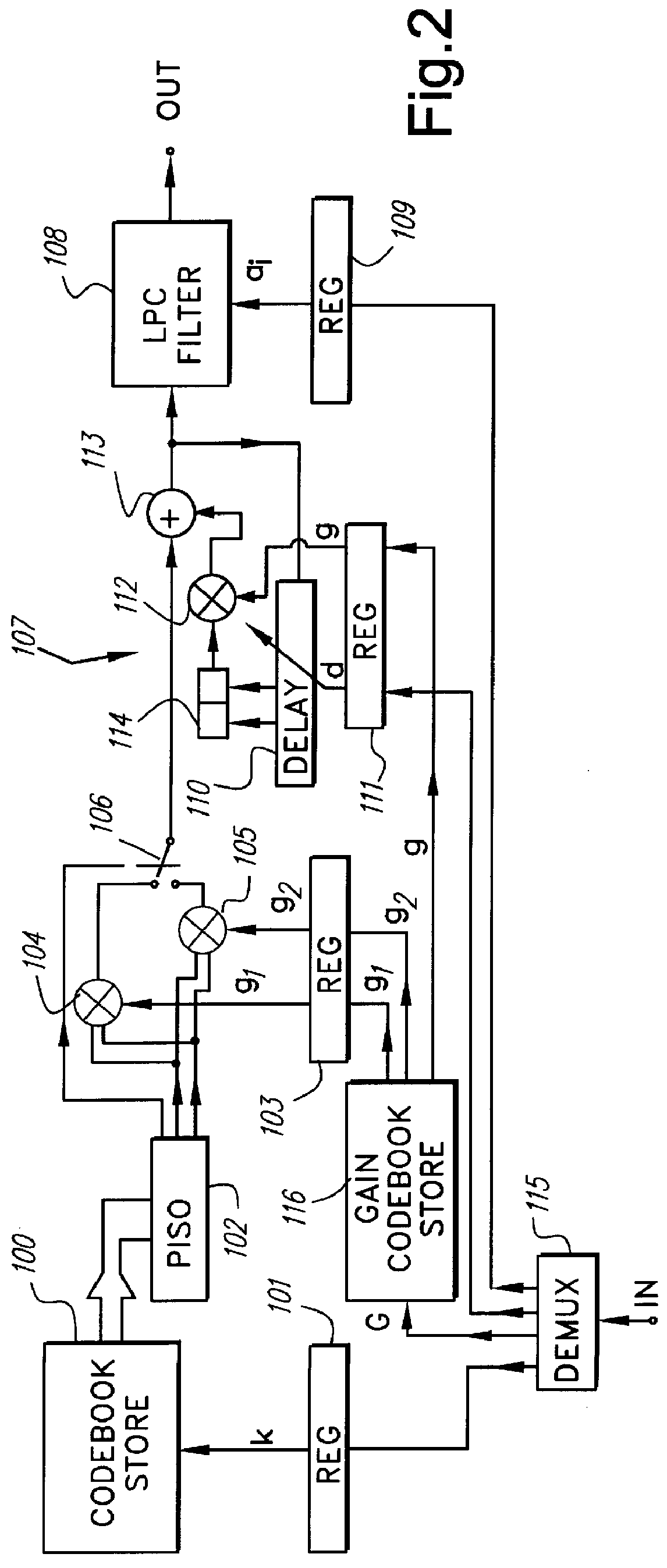
Before describing the speech coder, we first describe with reference to FIG. 2, a decoder to illustrate the manner in which the coded signals are used upon receipt to synthesise a speech signal. The basic structure involves the generation of an excitation signal, which is then filtered.

The filter parameters are changed once every 20 ms; a 20 ms period of the excitation signal being referred to as a block; however the block is assembled from shorter segments ("sub-blocks") of duration 5 ms.

Every 5 ms the decoder receives a codebook entry code k, and two gain values g.sub.1, g.sub.2 (though only one, or more than two, gain values maybe used if desired). It has a codebook store 100 containing a number (typically 128) of entries each of which defines a 5 ms period of excitation at a sampling rate of 8 kHz. The excitation is a ternary signal (i.e. may take values +1, 0 or -1 at each 125 .mu.s sampling instant) and each entry contains 40 elements of three bits each, two of which define th...


PUM


Abstract

PCT No. PCT / GB91 / 02291 Sec. 371 Date Jul. 27, 1993 Sec. 102(e) Date Jul. 27, 1993 PCT Filed Dec. 20, 1991 PCT Pub. No. WO92 / 11627 PCT Pub. Date Jul. 9, 1992A codebook excited speech coder analyzes speech to produce coefficients of a synthesis filter, the parameters of a long-term prediction filter (LTP) and a codeword indication one of a set of excitations. The results are transmitted to a receiver where they can be used to resynthesize the speech. The LTP and excitation analysis involve generation of impulse response products by adding additional terms to products already formed and storing them in a store. Multiplication of these products by excitation terms is performed using a pointer table storing precalculated addresses of locations in the store. If some excitations are shifted versions of others, some addresses can be obtained by modifying other addresses. The LTP analysis may include selection between a simple delay prediction and a prediction including the sum of two differently delayed terms, to provide improved predictor delay resolution.

Description

1. Field of the InventionThe present application relates to methods and apparatus for the coding of speech signals; particularly (though not exclusively) to code excited linear predictive coding (LPC) in which input speech is analysed to derive the parameters of an appropriate time-varying synthesis filter, and to select from a "codebook" of excitation signals those which, when (after appropriate scaling) supplied in succession to such a synthesis filter, produce the best approximation to the original speech. The filter parameters, codeword identifying codebook entries, and gains, can be sent to a receiver where they are used to synthesise received speech.2. Related ArtCommonly in such systems a long-term predictor is employed in addition to the LPC filter. This is best illustrated by reference to FIG. 1 of the accompanying drawings, which shows a block diagram of a decoder. The coded signal includes a codeword identifying one of a number of stored excitation pulse sequences and a g...

Claims


Application Information

Patent Timeline
Patent Type & Authority Patents(United States)
IPC IPC(8): G10L19/08G10L19/12G10L19/00G10L19/083
CPCG10L19/083G10L19/12G10L2019/0013G10L2019/0014
Inventor FREEMAN, DANIEL KENNETHWONG, WING-TAK KENNETHDAVIS, ANDREW GORDON
Owner BRITISH TELECOMM PLC
Why Eureka
Try Eureka