AM radio receiver

a radio receiver and receiver technology, applied in the field ofam radio receivers, can solve the problems of increasing tracking errors and increasing the cost of manufacture of such items, and achieve the effect of minimizing tracking errors

Inactive Publication Date: 2000-02-01
TOKO KABUSHIKI KAISHA
View PDF9 Cites 7 Cited by
  • Summary
  • Abstract
  • Description
  • Claims
  • Application Information

AI Technical Summary

Benefits of technology

It is an object of the present invention to provide a novel and improved AM radio receiver which is designed such that tracking error can be minimized without employing any such components as the aforementioned microcomputer, EPROM and D / A converter circuit.

Problems solved by technology

With the above-described conventional AM radio receiver, because of the radio-frequency tuning circuit and local oscillator circuit using variable capacitance diodes having different characteristics, the frequency difference between the oscillating frequency of the local oscillator circuit 72 and the tuning frequency of the radio-frequency tuning circuit 71 tends to be deviated far from the desired first intermediate frequency (10.7 MHz), thus resulting in an increased tracking error, when common tuning voltage is applied to the variable capacitance diodes of the radio-frequency tuning circuit 71 and the variable capacitance diode of the local oscillator circuit 72.
As will be seen, the above-mentioned conventional AM radio receiver is disadvantageous in that it requires such components as the D / A converter circuit, microcomputer and EPROM and thus the cost of manufacture thereof is increased accordingly.

Method used


Image

  • AM radio receiver
  • AM radio receiver
  • AM radio receiver

Examples


first embodiment

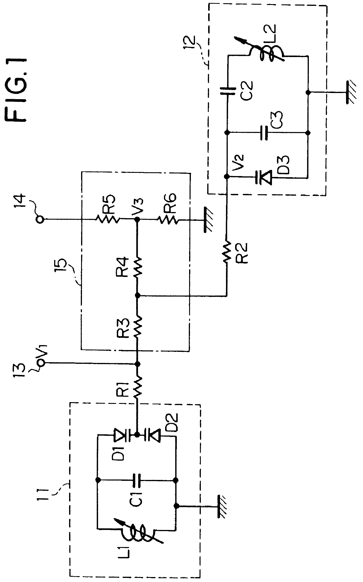
FIG. 1 illustrates the AM radio receiver according to the present invention, which includes a radio-frequency tuning circuit 11, local oscillator circuit 12, variable voltage supply terminal 13 connected to a variable voltage source, reference voltage supply terminal 14 coupled to a reference voltage source, and voltage adjustment circuit 15.

The radio-frequency tuning circuit 11 comprises a tuning coil L1, variable capacitance diodes D1 and D2, and capacitor C1. The variable capacitance diodes D1 and D2 have their cathodes connected together, with the anode of the variable capacitance diode D1 being tied to one end of the tuning coil L1, and with the anode of the variable capacitance diode D2 being coupled to the other end of the tuning coil L1. The capacitor C1 is connected in parallel with the tuning coil L1. The local oscillator circuit 12 comprises an oscillator coil L2, a variable capacitance diode D3, and capacitors C2 and C3 which serve to characterize tracking performance in...

second embodiment

FIG. 4 illustrates the circuit diagram of the AM radio receiver according to the present invention, which includes a radio-frequency tuning circuit 41, and local oscillator circuit 42.

In the radio-frequency tuning circuit 41, variable capacitance diodes D4 and D5 having their cathodes coupled together are connected in parallel with a tuning coil L3. In the local oscillator circuit 42, a capacitor C4 is connected in series with an oscillator coil L4, and a variable capacitance diode D6 is connected in parallel with the oscillator coil L4.

The radio-frequency tuning circuit 41 is connected to a variable voltage supply terminal 43 through a resistor R7. The local oscillator circuit 42 is coupled to the variable voltage supply terminal 43 through a voltage adjustment circuit 45.

In the voltage adjustment circuit 45, a variable resistor R10 is connected between a reference voltage supply terminal 44 and ground, and resistors R8 and R9 are connected in series between the variable resistor R...

third embodiment

FIG. 5 is a circuit diagram illustrating the AM radio receiver according to the present invention, which comprises a radio-frequency tuning circuit 51, local oscillator circuit 52, variable voltage supply terminal 53, reference voltage supply terminal 54, and voltage adjustment circuit 55.

The radio-frequency tuning circuit 51 comprises a tuning coil L5, and a pair of variable capacitance diodes D7 and D8 which, having their cathodes coupled together, are connected in parallel with the tuning coil L5.

The local oscillator circuit 52 comprises an oscillator coil L6, variable capacitance diodes D9 and D10, and a capacitor C5 which is connected in series with the oscillator coil L6. The variable capacitance diodes D9 and D10 are connected in parallel with the oscillator coil L6. C5, C6 and C7 are capacitors which serve to characterize tracking performance in the form of a quintic function, thereby minimizing tracking error. R12 is a resistor which feeds DC current.

The voltage adjustment ...


PUM


Abstract

In an AM radio receiver, a radio-frequency tuning circuit comprises a tuning coil, and variable capacitance diode elements connected to the tuning coil; a local oscillator circuit comprises an oscillator coil, a variable capacitance diode element connected in parallel with the oscillator coil, and a capacitance element connected in series with the oscillator coil; and tuning voltage is applied from a variable voltage source to the variable capacitance diode elements of the high-frequency tuning circuit, and to the variable capacitance diode element of the local oscillator circuit through a voltage adjustment circuit connected to the variable voltage source and a reference voltage source.

Description

BACKGROUND OF THE INVENTION1. Field of the InventionThe present invention relates to an AM radio receiver adapted for receiving amplitude-modulated signals, and more particularly it pertains to an AM radio receiver of the so-called up-conversion type, which comprises a radio-frequency tuning circuit for selecting amplitude-modulated signal received at antenna; a local oscillator circuit for generating an oscillating signal which is used in a first frequency conversion section to convert the receiving signal to an intermediate frequency signal having a higher frequency than that of the receiving signal.2. Description of the Prior ArtReferring to FIG. 7 of the accompanying drawings, there is shown a circuit diagram of prior-art AM radio receiver, which includes a radio-frequency tuning circuit 71 arranged to select an amplitude-modulated signal received at an antenna, and a local oscillator circuit 72 arranged to generate an oscillating signal for converting the receiving signal to an...

Claims


Application Information

Patent Timeline
Patent Type & Authority Patents(United States)
IPC IPC(8): H03J3/24H03J3/00H04B1/26H03J3/32H04B1/18
CPCH03J3/24
Inventor HATADA, SHIGERUSUZUKI, YUKIO
Owner TOKO KABUSHIKI KAISHA
Why Eureka
Try Eureka