Optical pickup device and optical disc drive

Inactive Publication Date: 2009-10-01
PANASONIC CORP
View PDF37 Cites 1 Cited by
  • Summary
  • Abstract
  • Description
  • Claims
  • Application Information

AI Technical Summary

Benefits of technology

[0024]It is therefore an object of the present invention to provide an optical pickup device and an optical disc drive that can not only reduce the fluctuation of the servo signals that will be caused due to the interference occurring on photodetectors while a read / write operation is being performed on any of various kinds of multilayer storage discs such as BD-R, BD-RE, DVD±R and DVD-RW but also get the read / write operation done with good stability even on an optical disc with a different guide groove width such as a DVD-RAM.
[0039]The optical pickup device and optical disc drive of the present invention define the sub-beam division boundary of a quadruple photodetector in a direction corresponding to the tracking radial direction, and does not detect it as a dead zone, in each of a photodetector for use in common in BDs and CDs and a photodetector for DVDs. By avoiding detecting light in an area where the interference fringes have two significantly different intensities, the fluctuation of a tracking error signal can be minimized in a multilayer optical disc such as a BD or a DVD.
[0041]Furthermore, by defining the sub-beam division boundary of a quadruple photodetector in a cross shape, and not detecting it as a dead zone, for the photodetector for use in common in BDs and CDs and the photodetector for DVDs, the fluctuation could be reduced not only in the tracking error signal for multilayer BDs or DVDs but also in the focus error signal as well. On top of that, if the division boundary has a narrower width in a tangential direction, which crosses the radial direction at right angles, than in the direction corresponding to the radial direction, then not only the harmful effect on the tracking error but also the fluctuation of the focus error signal could be both reduced.
[0042]Moreover, by defining the shielding width of the division boundary of the photodetector for DVDs to be either narrower than that of BDs or CDs or even equal to zero, the detrimental influence of shielding on the tracking error signal for DVD-RAMs can be minimized.
[0043]Consequently, the present invention provides an optical pickup device and an optical disc drive that can get a read / write operation done with good stability on not just single-layer or multilayer BD-R, BD-RE, DVD±R, DVD±RW and CD discs but also even DVD-RAMs as well.

Problems solved by technology

Strictly speaking, interference will also be caused by the light reflected from the surface of the optical disc.
However, such reflected light can be neglected because its light intensity is lower than that of the light reflected from the other storage layer.
Such a focus error is caused due to the thickness of the intermediate layer between the two storage layers.
As a result, the focus error and tracking error signals will fluctuate and the servo control may lose its stability.
In those optical pickup devices, the servo control could lose its stability due to the interference between the light reflected from the target storage layer and the light reflected from a non-target storage layer in a multilayer disc for the reasons described above.
That is why if the dead zone as disclosed in that document were provided in such a situation, then the tracking control signal would have a decreased level, thus possibly threatening the stability of the tracking control.

Method used


Image

  • Optical pickup device and optical disc drive
  • Optical pickup device and optical disc drive
  • Optical pickup device and optical disc drive

Examples


embodiment 1

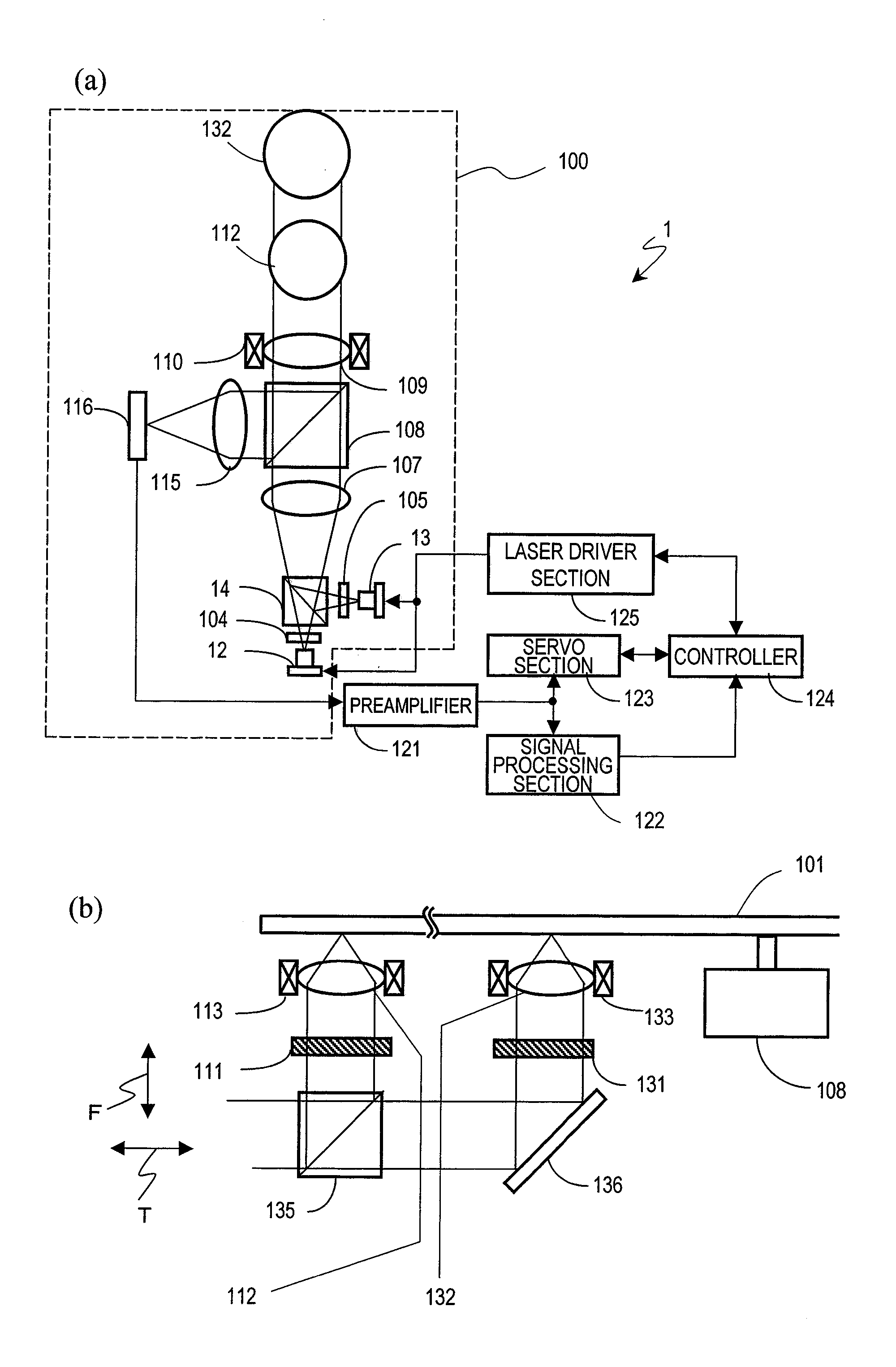
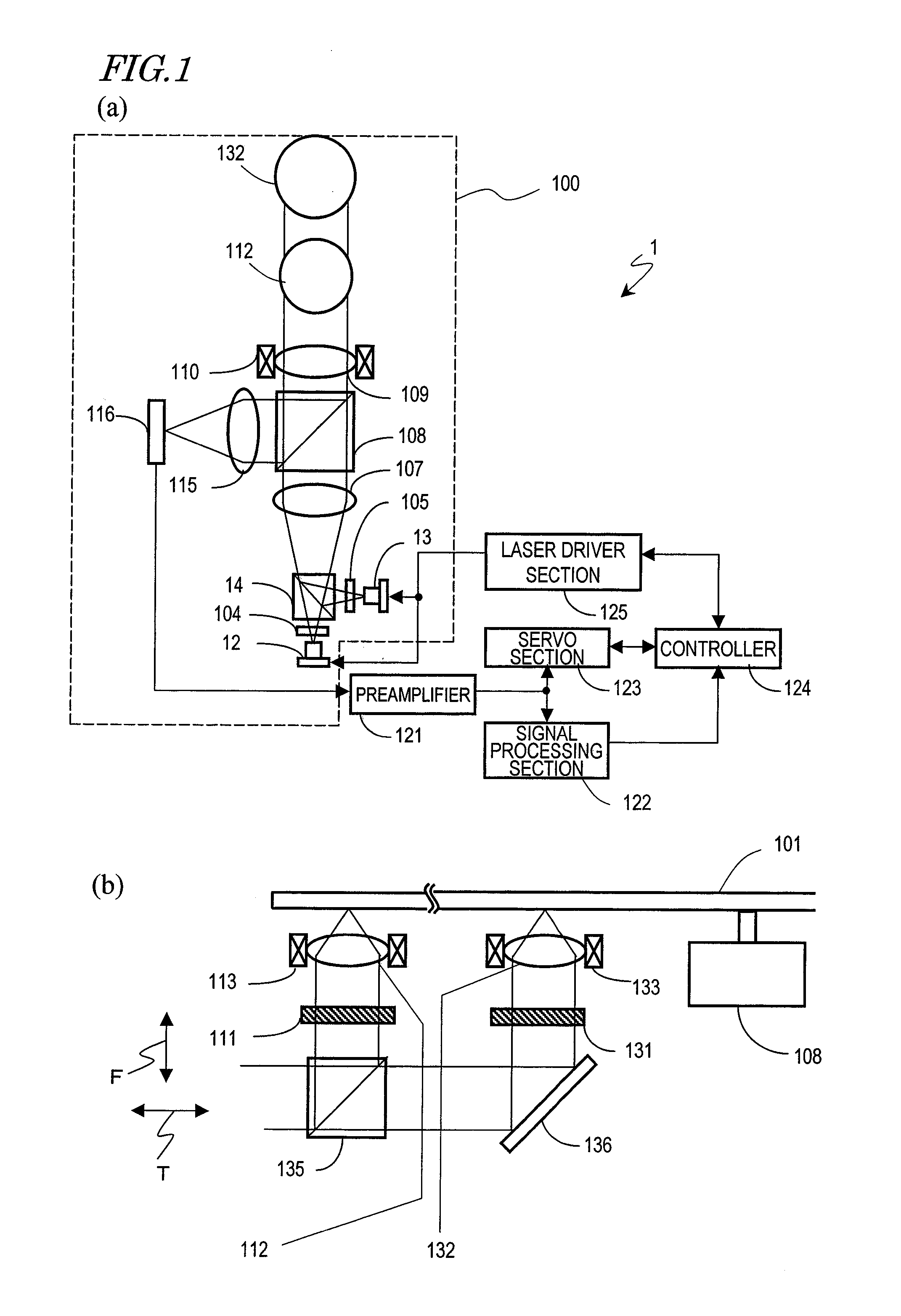
[0052]FIG. 1(a) illustrates a configuration for an optical disc drive 1 that can read and / or write information from / on BDs, DVDs and CDs that are compliant with three different standards.

[0053]The optical disc drive 1 includes an optical pickup device 100, a preamplifier 121, a signal processing section 122, a servo section 123, a controller 124, and a laser driver section 125. In some cases, the preamplifier 121 and the laser driver section 125 could be built in the optical pickup device 100.

[0054]The optical pickup device 100 is a so-called “three-wavelength compatible” type and can perform read and / or write operation(s) on an optical disc with a single or multiple storage layer(s).

[0055]First of all, it will be described how this optical pickup device works on BDs.

[0056]As shown in FIG. 1(a), in the optical pickup device 100, the light beam emitted from the blue laser diode (blue LD) of a blue LD package 12 is incident on a diffraction grating 104 and split into a zero-order main...

embodiment 2

[0073]This second preferred embodiment of the present invention also uses the optical disc drive 1 and optical pickup device 100 with the configuration shown in FIG. 1. Thus, the following description of this preferred embodiment will be focused on the differences from the first preferred embodiment described above.

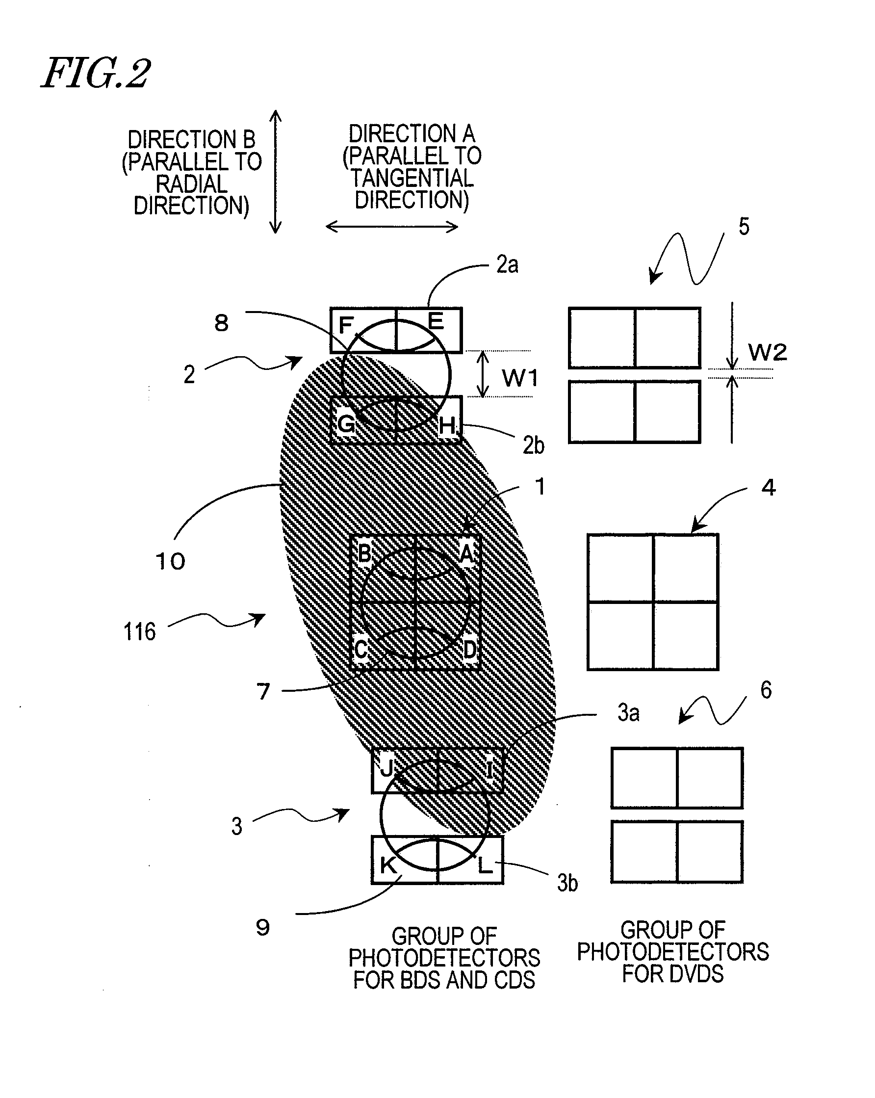
[0074]FIG. 5 illustrates photodetectors 41 to 46 for use in this preferred embodiment. These photodetectors 41 to 46 are arranged on the photodetector unit 116 shown in FIG. 1(a).

[0075]Among these photodetectors 41 to 46, each of the photodetectors 42 and 43 of the second type that receive the sub-beams when a BD or a CD is played is divided into four photosensitive areas. Specifically, the photodetector 42 is divided into photosensitive areas E, F, G and H and the photodetector 43 is divided into photosensitive areas I, J, K and L. A dead zone in a cross shape is arranged between those four photosensitive areas in each of the photodetectors 42 and 43.

[0076]The respective...


PUM


Abstract

An optical pickup device according to the present invention includes: first and second light sources that are driven selectively and that emit blue and red light beams, respectively; an optical element for splitting the blue and red light beams emitted into main and sub-blue beams and main and sub-red beams, respectively; first and second photodetectors that receive the main and sub-blue beams reflected from the optical disc, thereby outputting electrical signals; and third and fourth photodetectors that receive the main and sub-red beams reflected from the optical disc, thereby outputting electrical signals. A dead zone that outputs no electrical signal representing the intensity of the light received is provided for respective parts of the second and fourth photodetectors.

Description

BACKGROUND OF THE INVENTION[0001]1. Field of the Invention[0002]The present invention relates to an optical pickup device and an optical disc drive including the same optical pickup device.[0003]2. Description of the Related Art[0004]An optical pickup device including a plurality of light sources that operate at mutually different wavelengths and photodetectors that are provided for the respective light sources, i.e., a so-called “multi-wavelength optical pickup device”, has been developed. Examples of such multi-wavelength optical pickup devices include a three-wavelength optical pickup that has a light source that operates at a wavelength falling within the blue spectral range for Blu-ray Discs (BDs), a light source that operates at a wavelength falling within the red range for DVDs, and a light source that operates at an infrared wavelength for CDs.[0005]Some of those optical disc drives perform a tracking control by a so-called “three-beam method”, according to which a single li...

Claims


Application Information

Patent Timeline
IPC IPC(8): G11B7/00
CPCG11B7/0903G11B2007/0006G11B7/131G11B7/1275
Inventor KAYAMA, HIROSHIMOMOO, KAZUO
Owner PANASONIC CORP
Why Eureka
Try Eureka