A sample and hold circuit

A technology of sample and hold circuit and resistance, applied in electrical components, electrical signal transmission systems, instruments, etc., can solve the problem of inability to apply low power supply voltage, achieve high bandwidth, and minimize tracking errors.

Active Publication Date: 2022-04-08
UNIV OF ELECTRONICS SCI & TECH OF CHINA
View PDF4 Cites 0 Cited by
  • Summary
  • Abstract
  • Description
  • Claims
  • Application Information

AI Technical Summary

Problems solved by technology

[0004] Aiming at the limitation of the above-mentioned traditional sample and hold circuit in terms of signal amplitude, which cannot be applied to low power supply voltage, the present invention proposes a sample and hold circuit, which is based on the switched capacitor technology. By adding a feedback resistor at the input end and the structure of the bias current source, the input and the output are all connected with resistors, so that the signal swing of the present invention can be close to the power rail so that the signal-to-noise ratio is maximized; It works under low voltage, and overcomes the limitation of the threshold value on the operation of the sample-and-hold circuit at low voltage in the traditional technology, and can work at a low power supply voltage of 1.1V; the minimum power supply voltage of the sample-and-hold circuit proposed by the present invention is the maximum input common-mode voltage The drain-source voltage of the current tube is added, thus realizing the operation under the low supply voltage

Method used


Image

  • A sample and hold circuit
  • A sample and hold circuit
  • A sample and hold circuit

Examples


Embodiment Construction

[0027] The technical solution of the present invention will be described in detail below in conjunction with the accompanying drawings and specific embodiments.

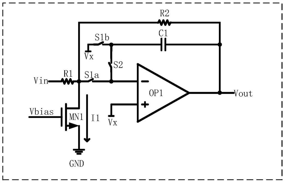
[0028] Such as figure 1 Shown is a sample-and-hold circuit proposed by the present invention, including a first operational amplifier OP1, a first switch S1a, a second switch S1b, a third switch S2, a first resistor R1, a second resistor R2, a first NMOS transistor MN1 and the first capacitor C1, one end of the first resistor R1 is used as the input end of the sample-and-hold circuit, and the other end is connected to the drain of the first NMOS transistor MN1, one end of the first switch S1a, and connected to the first operational amplifier after passing through the second resistor R2 The output end of OP1; the negative input end of the first operational amplifier OP1 is connected to the other end of the first switch S1a and one end of the third switch S2, and its positive input end is connected to one end of the se...


PUM


Abstract

A sample and hold circuit, comprising a first operational amplifier, a first switch, a second switch, a third switch, a first resistor, a second resistor, a first NMOS transistor and a first capacitor, one end of the first resistor is used as a sample and hold circuit The other end is connected to the drain of the first NMOS tube, one end of the first switch and connected to the output end of the first operational amplifier after passing through the second resistor; the negative input end of the first operational amplifier is connected to the other end of the first switch One terminal and one terminal of the third switch, the positive input terminal is connected to one terminal of the second switch and the common mode voltage, and the output terminal is used as the output terminal of the sample and hold circuit and connected to the other terminal of the second switch and the third switch after passing through the first capacitor The other end: the gate of the first NMOS transistor is connected to the bias voltage, and the source is grounded. The input end and the output end of the present invention are connected with polysilicon resistors, and the signal swing is close to the power supply rail so as to maximize the signal-to-noise ratio. In addition, a current source tube is provided so that the present invention can work normally under low power supply voltage.

Description

technical field [0001] The invention relates to electronic circuit technology, in particular to a sample and hold circuit. Background technique [0002] With the continuous development of digital signal processing technology, the digitization and integration of electronic systems is an inevitable trend. Most of the signals in reality are continuously changing analog quantities. The analog-to-digital converter (ADC) can convert the continuously changing analog quantities into digital signals and input them into the digital system for processing and control. Therefore, the ADC will be used in the future mixed signal system An integral part of the design. It is often necessary to integrate an ADC with a digital signal processor (DSP) in a design. As supply voltages for advanced CMOS processes continue to decrease for reliability reasons, ADCs integrated with DSPs need to operate within the same low supply voltage range. [0003] The sample-and-hold circuit is the front-end c...

Claims


Application Information

Patent Timeline
Patent Type & Authority Patents(China)
IPC IPC(8): H03M1/54H03M1/12
CPCH03M1/54H03M1/124
Inventor 李泽宏仪梦帅胡任任洪至超杨耀杰杨尚翰蔡景宜
Owner UNIV OF ELECTRONICS SCI & TECH OF CHINA
Why Eureka
Try Eureka