Freely rotating step-in snowboard binding

a step-in, free-rotating technology, applied in the field of snowboard binding, can solve the problems of not being able to allow the snowboarder to rotate the feet, the binding fails for the same, and the snowboarder cannot be able to do the same, so as to improve the snowboard binding system, improve the comfort and flexibility, and facilitate the binding. the effect of the binding system

Inactive Publication Date: 2000-02-08
BUZBEE DOUGLAS C
View PDF15 Cites 34 Cited by
  • Summary
  • Abstract
  • Description
  • Claims
  • Application Information

AI Technical Summary

Benefits of technology

Accordingly, one object and advantage is to provide an improved snowboard binding system.
A second object of this invention is to provide a snowboard binding system that allows the snowboarder to rotate the front foot without requirement of manual operation.
A third object and advantage is to provide a snowboard binding system that allows the snowboarder to place the front foot along the long axis of the snowboard (longitudinally) after having reached the end of the run and having entered the lift line. This action is much like a skateboarder placing the front foot longitudinally along the skateboard during the action of propelling the skateboard with the rear foot.
A fourth object is to provide a snow

Problems solved by technology

Problems 1 and 2 above have been recognized in previous patents but have not been satisfactorily solved.
However, his binding requires manual operation to change the angular positioning of the feet and therefore fails to allow the snowboarder to rotate the feet during operation of the snowboard.
However their binding fails for the same reasons that Donovan's does; it requires a manual adjustment to rotate the foot.
However, these bindings do not satisfactorily resolve these problems for the following three reasons: (1) Once the foot is released from the board, the soft boot suppor

Method used


Image

  • Freely rotating step-in snowboard binding
  • Freely rotating step-in snowboard binding
  • Freely rotating step-in snowboard binding

Examples


Embodiment Construction

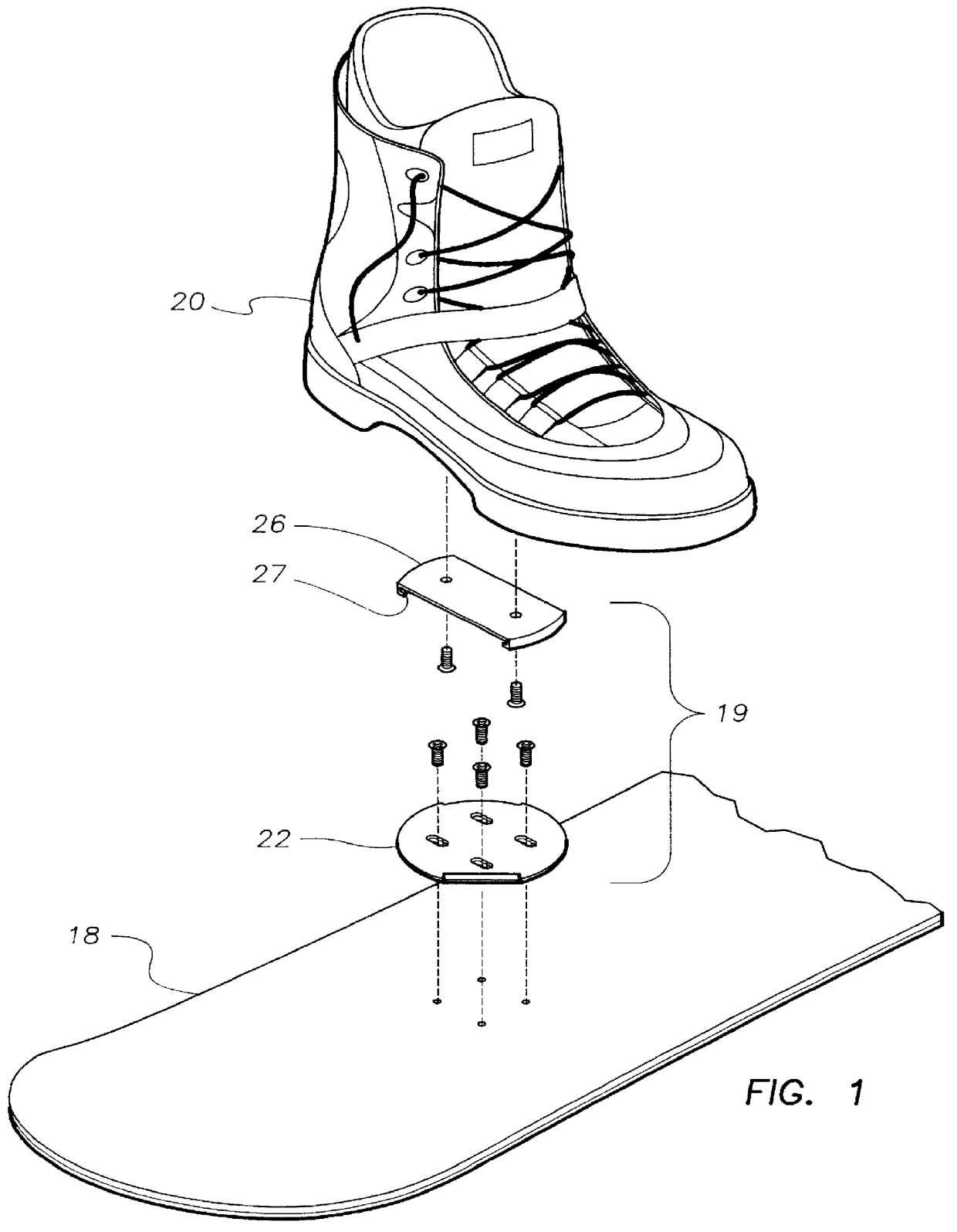
FIG. 1 is an expanded view of a preferred binding assembly 19. A circular binding base 22 is secured to a snowboard 18 via several screw receiving holes in base 22. A four-hole pattern is illustrated in these figures which is compatible with many presently available snowboards. A boot catch structure 26 is secured to a boot 20 via two screw receiving holes in the boot 20.

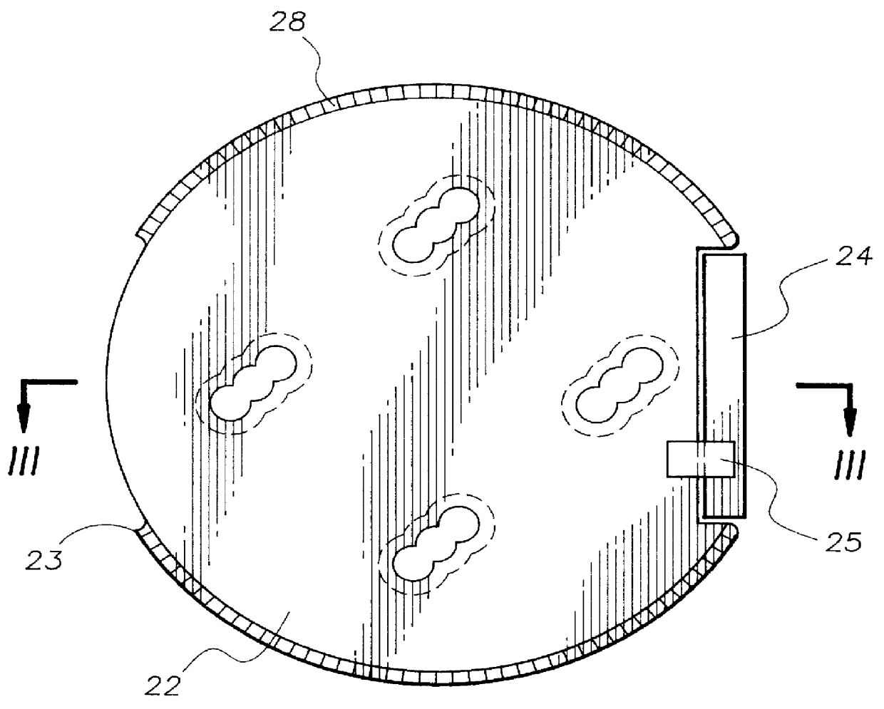
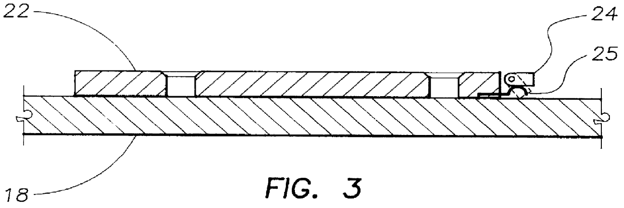
FIG. 2 is a bottom plan view of binding base 22 which is comprised of a circular disk with two opposing binding base flanges 23 projecting from the disk, each having the same arc length, and being opposite each other (symmetrical). Flanges 23 have ridges 28 placed radially along the underside of flange 23. A locking plate 24 is placed between one of the spaces between the flanges. Plate 24 consists of a small flat piece of rigid material (e.g., steel) attached to base 22 via a hinge and equipped with a spring 25 to maintain plate 24 in the more or less horizontal position unless manually depressed. Plate 24, spring ...


PUM


Abstract

An improved snowboard binding system allows the snowboarder to maintain full control of the snowboard while also allowing the snowboarder to rotate the feet during the operation of the snowboard without the requirement of manual adjustment. A binding base (22) is attached to the snowboard and contains a circular, downward-facing surface (23) having several discontinuities. A boot catch structure (26) is attached to the user's boot and has a corresponding number of upward facing planar surfaces (27) that fit into the base surface discontinuities. Engagement of the binding is accomplished by the insertion of the boot catch into the binding base and relative rotation of the two parts. The binding system is equipped with a locking plate (24) that guards against accidental release of the binding system.

Description

1. Field of the InventionThis invention relates to the field of snowboarding. Specifically, it relates to a snowboard binding system that allows the snowboarder to step directly into the binding, and that allows limited rotational movement of the feet after engagement of the binding and during operation of the snowboard, all without manual operation.2. Snowboarding and Its ProblemsSnowboarding is essentially wave surfing applied to down-hill skiing terrain and conditions. While the skier uses one long plank attached to each foot to glide downhill over the snow, the snowboarder attaches both feet transversely to one shorter, wider plank with which she glides over the snow. The motion of snowboarding is much more similar to surfing than to skiing.Snowboarding has grown in popularity over the past decade or so, to the point that it is becoming almost as popular as skiing. In fact, with younger generations of ski resort clients, snowboarding is already more broadly undertaken, which sug...

Claims


Application Information

Patent Timeline
IPC IPC(8): A63C9/00A63C10/10A63C10/18A63C10/28
CPCA63C10/10A63C10/18A63C10/28Y10T403/7005A63C2203/54
Inventor BUZBEE, DOUGLAS C.
Owner BUZBEE DOUGLAS C
Why Eureka
Try Eureka