Water-cooled thrust combustion grate

a technology of combustion grate and thrust, which is applied in the direction of solid bar grate, combustion process, lighting and heating apparatus, etc., can solve the problems of reducing the service life of the entire grate, skewing of the grate plate, and high leverage for

Inactive Publication Date: 2000-02-15
DOIKOS INVESTIMENTS LTD
View PDF5 Cites 27 Cited by
  • Summary
  • Abstract
  • Description
  • Claims
  • Application Information

AI Technical Summary

Problems solved by technology

One of the disadvantages of this means of driving the movable grate plates is that any small item that becomes jammed at the side between the grate plate and the outer side panel can cause the grate plate to skew to the side; that is, as seen from the top, the plate no longer lies exactly parallel to the adjoining stationary grate plates.
If it is then displaced while in this position, high leverage forces occur, as a result of which the plate comes into contact with the outer side panels.
The wear caused by the enormous friction force is considerable and reduces the service life of the entire grate.
Furthermore, the drive means is designed in such a way that an individual drive for each movable grate plate, which would be desirable to optimize the combustion process, could only be installed at phenomenal cost.
Even with this construction, skewing to the side is impossible to avoid.
If a small particle gets jammed between the grate plate and an outer side panel, very high friction forces occur which, firstly, require correspondingly large hydraulic cylinders to overcome them and, secondly, cause correspondingly high wear.

Method used


Image

  • Water-cooled thrust combustion grate
  • Water-cooled thrust combustion grate
  • Water-cooled thrust combustion grate

Examples


Embodiment Construction

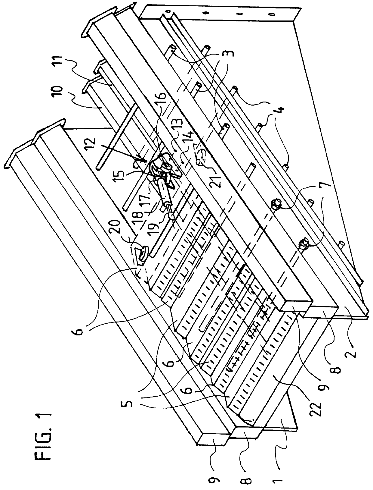
The basic structure of the thrust combustion grate of this invention with its essential elements is shown most clearly in FIG. 1. FIG. 1 shows a portion of a length of the grate in a perspective view, as it would look like during assembly, that is with some grate plates missing, giving a clear view of the substructure. The grate is sloped downwards in the direction of conveyance. Two vertical steel walls 1,2 disposed parallel to each other, are stably connected to each other by a plurality of distancing bars 3,4. These distancing bars 3,4 run crosswise to the orate and extend across the inside width between the two vertical steel walls 1,2 at two different levels. The two vertical steel walls 1,2 in accordance with one embodiment of this invention comprise a plurality of steel panels or parts screwed together in a suitable manner. Distancing bars 3,4, threaded at both ends, penetrate the two vertical steel walls 1, 2 and are screwed tightly to the vertical steel walls 1,2 by means o...


PUM


Abstract

A thrust combustion grate for burning refuse having altemately stationary (5) and movable (6) hollow grate plates (5,6) in a stairway formation, that rest on each other with their front underedge. The grate plates extend across the entire width of the grateway. The movable grate plates (6) are each driven by a hydraulic cylinder-piston unit (18,19). To the sides, the grateway is limited by panels of water-cooled conduits (8,9), which, in the longitudinal direction, each consist of at least two sections sealingly flanged together. The panels are rigidly screwed to each other by a plurality of horizontally disposed distancing bars (3,4) running perpendicular thereto. Running between the panels are two additional conduits (10,11) flanged together in the same way, for feeding primary air and cooling water, which are fixed to certain individual distancing bars (3,4). The back sides of the stationary grate plates (5) each rest on one distancing bar (3) while the back sides of the movable grate plates (6) rest on at least one steel roller (16,17) with a horizontal axis, with each side of their front sides being guided along a steel roller (20,21) whose axis runs perpendicular to the grate plate (6). The front portions of the grate plates (6) form by primary air slots (25).

Description

1. Field of the InventionThis invention relates to a water-cooled thrust combustion grate for refuse combustion plants that is particularly well suited for the combustion of refuse and waste with high heating values. Such thrust combustion grates have stationary and movable grate levels comprising grate plates or a row of grate bars, with the grate plates resting on top of each other in a stair-like manner. These thrust combustion grates can be assembled so that the combustion bed is essentially horizontal, or possibly inclined, with slopes of up to 20 degrees or more being usual. The grate plates are preferably made from sheet steel and form panel-shaped hollow elements which extend across the entire width of a grateway, through which water is fed as a cooling medium. Every second grate plate is movable, allowing it to perform a stoking or transporting stroke. In the case of a forward feed grate, the leading edge of the movable grate plates pushes material to be combusted forward o...

Claims


Application Information

Patent Timeline
Patent Type & Authority Patents(United States)
IPC IPC(8): F23H7/00F23H3/00F23H3/02F23H7/08F23G5/00
CPCF23H3/02F23H7/08F23H2900/03021F23H11/12
Inventor STIEFEL, JAKOB
Owner DOIKOS INVESTIMENTS LTD
Why Eureka
Try Eureka