Method for window formation in wellbore tubulars

a wellbore tubular and window technology, applied in the direction of drilling machines and methods, directional drilling, borehole/well accessories, etc., can solve the problems of high cost of rig time and add to the risk of problems

Inactive Publication Date: 2000-02-15
WEATHERFORD TECH HLDG LLC
View PDF188 Cites 143 Cited by
  • Summary
  • Abstract
  • Description
  • Claims
  • Application Information

AI Technical Summary

Benefits of technology

The present invention, in one embodiment, discloses a method for forming an opening in a wellbore casing which includes introducing an apparatus including a whipstock or other drill bit or mill diversion device into the wellbore and locating it at a desired point in the wellbore. In one aspect a drill bit is releasably connected to the diversion device. In one aspect a window mill is releasably connected to the whipstock. To create a hole through which drilling of the formation adjacent the hole is possible or to initiate a starting hole or slot for milling in the casing, a shaped charge of explosive is attached to the apparatus. In one aspect the charge is attached to a drill bit; in one aspect to the diversion device; and in another aspect to the window mill. In one aspect the charge is attached below the window mill. The explosive charge is properly designed to form a hole of desired shape and configuration in the casing without damaging the whipstock, drill bit, window mill, or adjacent casing; and, in certain aspects, to form the beginning of a lateral bore in formation adjacent to a wellbore tubular. The explosive is also designed to create a minimum of debris in the wellbore.
In one embodiment an explosive charge (e.g. a linear jet shape charge) is run into a cased wellbore with a whipstock so that the charge is directed 180 degrees from the whipstock concave. It is detonated at the depth that corresponds to the depth of the window mill at which coring is anticipated. This charge cuts an axial slot out of the casing wall so that when the mill encounters the slot, there is no casing on its centerline (casing in that area having been previously removed by the charge), thus preventing coring.
Such systems for forming a radial ledge in casing for facilitating milling of the casing;

Problems solved by technology

Rig time is very expensive and multiple trips take time and add to the risk that problems will occur.
Another problem encountered in certain typical milling operations is "coring".

Method used


Image

  • Method for window formation in wellbore tubulars
  • Method for window formation in wellbore tubulars
  • Method for window formation in wellbore tubulars

Examples


Embodiment Construction

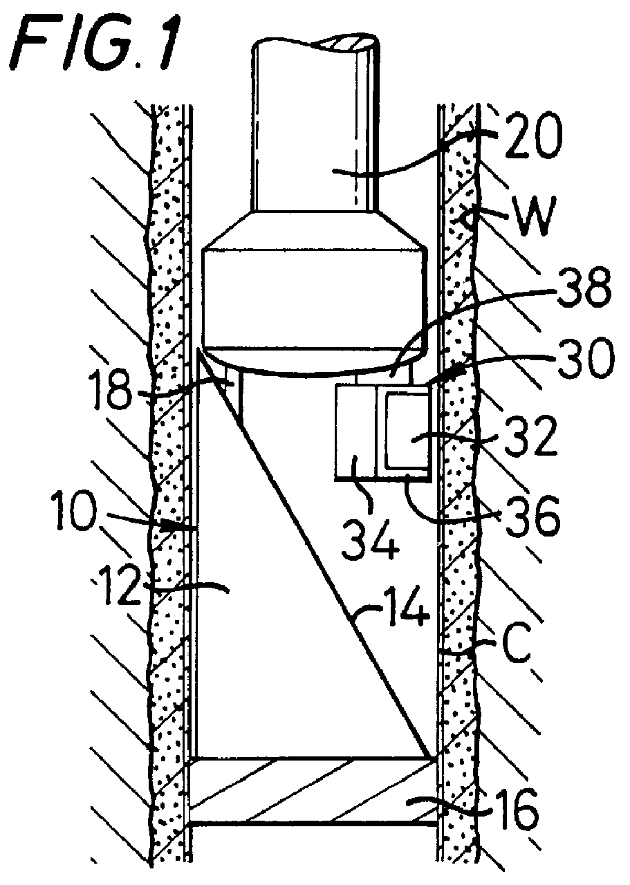
Referring now to FIG. 1, a system 10 according to the present invention is shown schematically in a wellbore W cased with casing C. The system 10 includes a whipstock 12 with a concave face 14 anchored by an anchor device 16 in the wellbore W. A window mill 20 is releasably connected to the whipstock 12 e.g. with a shear stud 18 (or with an hydraulic release device).

An explosive charge system 30 is secured to the whipstock 12 (e.g. by any suitable securement apparatus, device, or method) (or to the window mill 20). Shock attenuation material 36 is preferably disposed on the sides of the explosive charge except the side facing the casing. The system 30 includes a typical amount of an explosive 32 and a typical detonator device 34. The explosive 32 may be detonated at a desired moment in time using any suitable known apparatus or mechanism.

Detonation may be effected by employing drill string pressure, annulus pressure, pressure sequencing, mechanical devices (e.g. bar drop through dri...


PUM


Abstract

New systems and methods have been invented for explosively forming openings, ledges, windows, holes, and lateral bores through tubulars such as casing, which openings may, in cerain aspects, extend beyond the casing into a formation through which a wellbore extends. In certain aspects openings (e.g. ledges, initial, or completed windows) in wellbore tubulars (e.g. tubing or casing) are made using metal oxidizing systems, water jet systems, or mills with abrasive and / or erosive streams flowing therethrough and / or therefrom.

Description

1. Field of the InventionThis invention is related to apparatuses and methods for forming a window in a wellbore tubular, e.g. casing, in a wellbore.2. Description of Related ArtThe practice of producing oil from multiple radially dispersed reservoirs, through a single primary wellbore has increased dramatically in recent years. To facilitate this, "kick-off" technology has been developed and continues to grow. This technology allows an operator to drill a vertical well and then continue drilling one or more angled or horizontal holes off of that well at chosen depth(s). Because the initial vertical wellbore is often cased with a string of tubular casing, a "window" must be cut in the casing before drilling the "kick-off". In certain prior art methods windows are cut using various types of milling devices and one or more "trips" of the drill string are needed. Rig time is very expensive and multiple trips take time and add to the risk that problems will occur.Another problem encount...

Claims


Application Information

Patent Timeline
Patent Type & Authority Patents(United States)
IPC IPC(8): E21B7/06E21B29/00E21B7/04E21B29/02E21B29/06E21B43/11E21B43/1185E21B43/114E21B43/116F42D3/00
CPCE21B7/061E21B29/005E21B29/02E21B29/06E21B43/114E21B43/116E21B43/11852E21B43/11855F42D3/00
Inventor HAUGEN, DAVID M.
Owner WEATHERFORD TECH HLDG LLC
Why Eureka
Try Eureka