Low profile antenna assembly for use in cellular communications

a low-profile, antenna array technology, applied in the structural form of individual energised antenna arrays, resonant antennas, radiating elements, etc., can solve the problems of reducing the capacity reducing the efficiency of these additional sectors, and affecting the performance of the system

Inactive Publication Date: 2000-02-15
NORTEL NETWORKS LTD
View PDF10 Cites 39 Cited by
  • Summary
  • Abstract
  • Description
  • Claims
  • Application Information

AI Technical Summary

Problems solved by technology

However, when considering utilizing more than three (3) sectors of coverage, the additional sectors increase in capacity is not as efficient due to overlapping coverage from the antennas' radiation pattern into the additional sectors.
More particularly, current beamwidth cellular antennas produce significant sidelobes, which in turn scatter energy into the adjacent sectors, and effectively reduce the capacity efficiency of these additional sectors.
In most cases, the sidelobe peak gain is within twelve (12) dB of the main beam peak gain and in many cases the sidelobes gain can be five (5) to six (6) dB below the mainlobe gain of the antenna which from a system performance standpoint may be unacceptable.
Furthermore, cellular antenna assemblies are quite large due to current antenna design constraints when designing in the cellular phone frequency range of 800 Mhz and 1900 Mhz.
This results in antennas being installed in urban areas and onto buildings with bulky and unsightly installation hardware such as long masts.
Additionally, current antennas are designed with fixed radiation patterns having the main beam at boresight resulting in complicated and expensive mounting brackets that must incrementally swivel in the horizontal and vertical planes to achieve the sector coverage desired.

Method used


Image

  • Low profile antenna assembly for use in cellular communications
  • Low profile antenna assembly for use in cellular communications
  • Low profile antenna assembly for use in cellular communications

Examples


Embodiment Construction

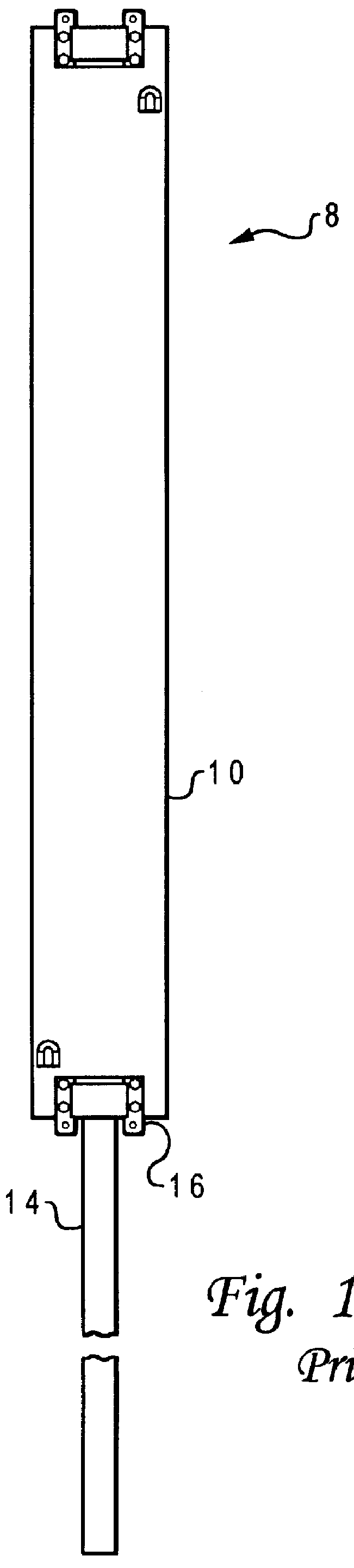
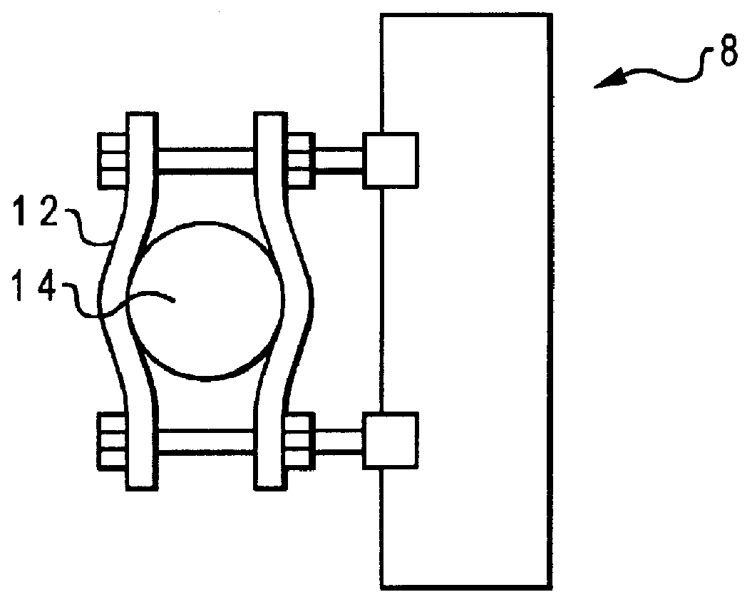
Referring now to the drawings wherein like reference numerals refer to like and corresponding parts throughout, a prior art antenna assembly for use in cellular communications is shown in FIGS. 1 and 2. Referring now to FIGS. 1 and 2, the prior art antenna assembly 8 comprises an elongated antenna housing 10 supported by a long mast 14 which is bolted to the side of a building structure and holds the antenna housing 10 by a plurality of clamps 12. As shown in FIG. 1, the prior art antenna assembly 8 is quite large and unsightly due to current antenna designs used for the cellular phone frequency range of 800 Mhz and 1900 Mhz. The prior art antenna (not shown) located within antenna housing 10 is designed with a fixed radiation pattern resulting in an expensive mounting bracket 16 that incrementally swivels in the horizontal and vertical planes to achieve the sector coverage desired.

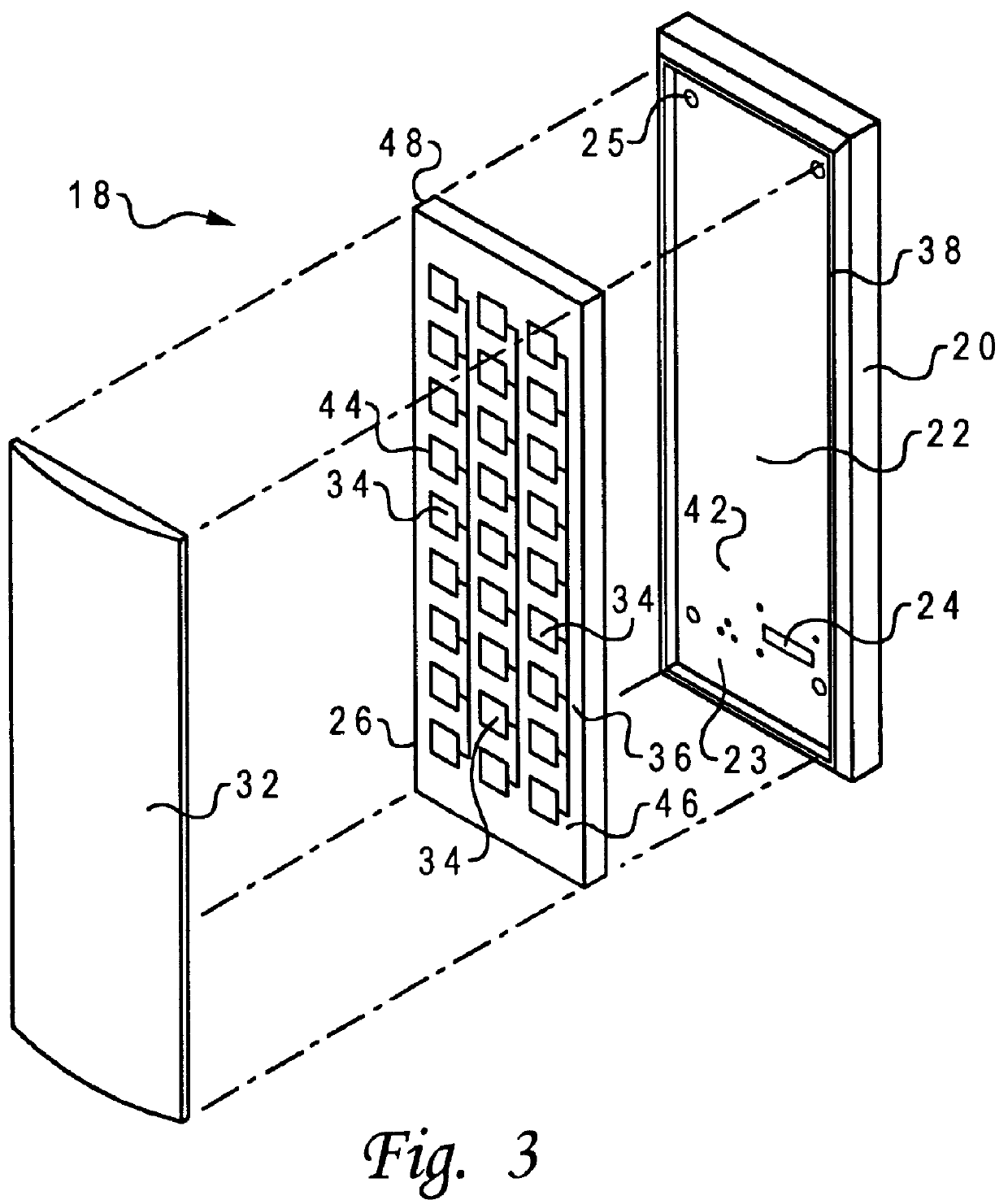
The low profile antenna assembly of the present invention is generally indicated by numeral 18 and sol...


PUM


Abstract

The low profile antenna assembly comprises a generally rectangular frame member housing a planar antenna. A radar absorbing material is attached to the front side of the housing with a radome covering the front side of the planar antenna and attached to the frame member. The planar antenna is a microstrip array fed by a beam forming network that uses either delay lines or phase shifters to electronically steer the antenna pattern horizontally and vertically. The antenna assembly is weatherproofed, painted and flush mounted against a building surface for camouflaging the antenna assembly from observers at a distance.

Description

1. Technical FieldThe present invention relates in general to reduced sidelobe antenna array assemblies, and in particular to low profile antenna array assemblies for use in cellular communications having low visual profile site capabilities when mounted against a building surface.2. Description of the Related ArtIn cellular communications it is common practice to utilize a three (3) sector antenna configuration for a given base station where a sector refers to the area coverage provided by the beamwidth of the main beam (also known as the mainlobe) of the antennas' radiation pattern. The use of pointing the mainlobe of an antenna for a given sector has produced significant advantages in modern day cellular system technologies. More specifically, sectorization reduces co-frequency interference, allowing more efficient frequency planning and the associated capacity improvements in Advanced Mobile Phone Systems (AMPS), Time Division Multiplexed Access (TDMA), and Global System Mobile ...

Claims


Application Information

Patent Timeline
Patent Type & Authority Patents(United States)
IPC IPC(8): H01Q3/36H01Q21/06H01Q3/30H01Q1/38H01Q3/40H01Q1/24
CPCH01Q1/246H01Q1/38H01Q3/36H01Q3/40H01Q21/065
Inventor BERGEN, SCOTT P.ROBERTSON, FREDERICK A.
Owner NORTEL NETWORKS LTD
Why Eureka
Try Eureka