Device for converting a rotary motion into an axial motion

Inactive Publication Date: 2000-02-22
HEHL KARL
View PDF19 Cites 43 Cited by
  • Summary
  • Abstract
  • Description
  • Claims
  • Application Information

AI Technical Summary

Benefits of technology

Hence, from the outside, we have the picture of a piston rod that plunges into a cylinder, since due to the translational motion between tube and the tubular element surrounding the shaft coaxially, rotation is no longer visible. This creates the structural prerequisites for a sealing on a smooth surface without rotation between the parts to be sealed against one another, so that the protection of the mechanical drive against dirt is increased. If the interior of the tube is closed on the side opposite to the seal, it is possible to reliably apply an oil lubrication over a long period of time which, compared with known drives, increases efficiency and working life of the device. At the same time the drive becomes quieter, and the inside space is cooled by the oil volume in the inner chamber. Additionally, the shaft diameter can be adjusted to its respective task, since the shaft no longer needs to perform the sealing function at the same time.

Problems solved by technology

However, this protective function is lessened by the fact that the shaft bearing the threaded spindle rotates relative to the tubular nut in the sealing region, so that not only the sealing is subject to an additional wear, but also dirt particles cannot be reliably kept away from the inner chamber over the long term (See DE AS 1 043 743).
However, it is not intended to uncouple the drive from the force flow by use of these elastic elements.

Method used


Image

  • Device for converting a rotary motion into an axial motion
  • Device for converting a rotary motion into an axial motion
  • Device for converting a rotary motion into an axial motion

Examples


Embodiment Construction

The invention will now be described in more detail, by example, with reference to the accompanying figures. The embodiments are merely examples, which should not limit the inventive concept to any particular physical configuration.

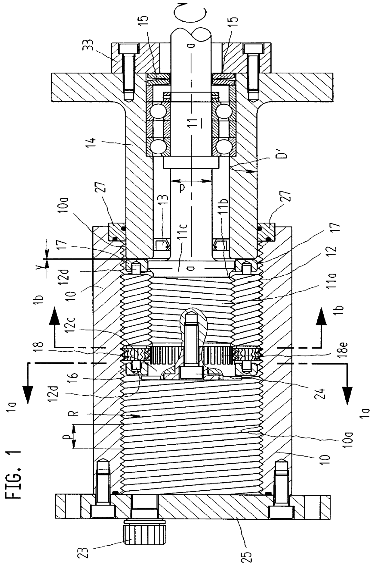
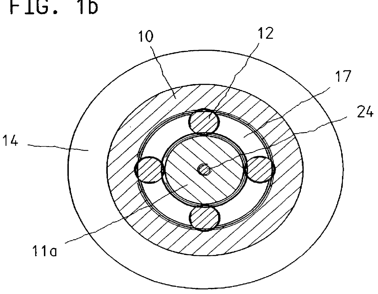
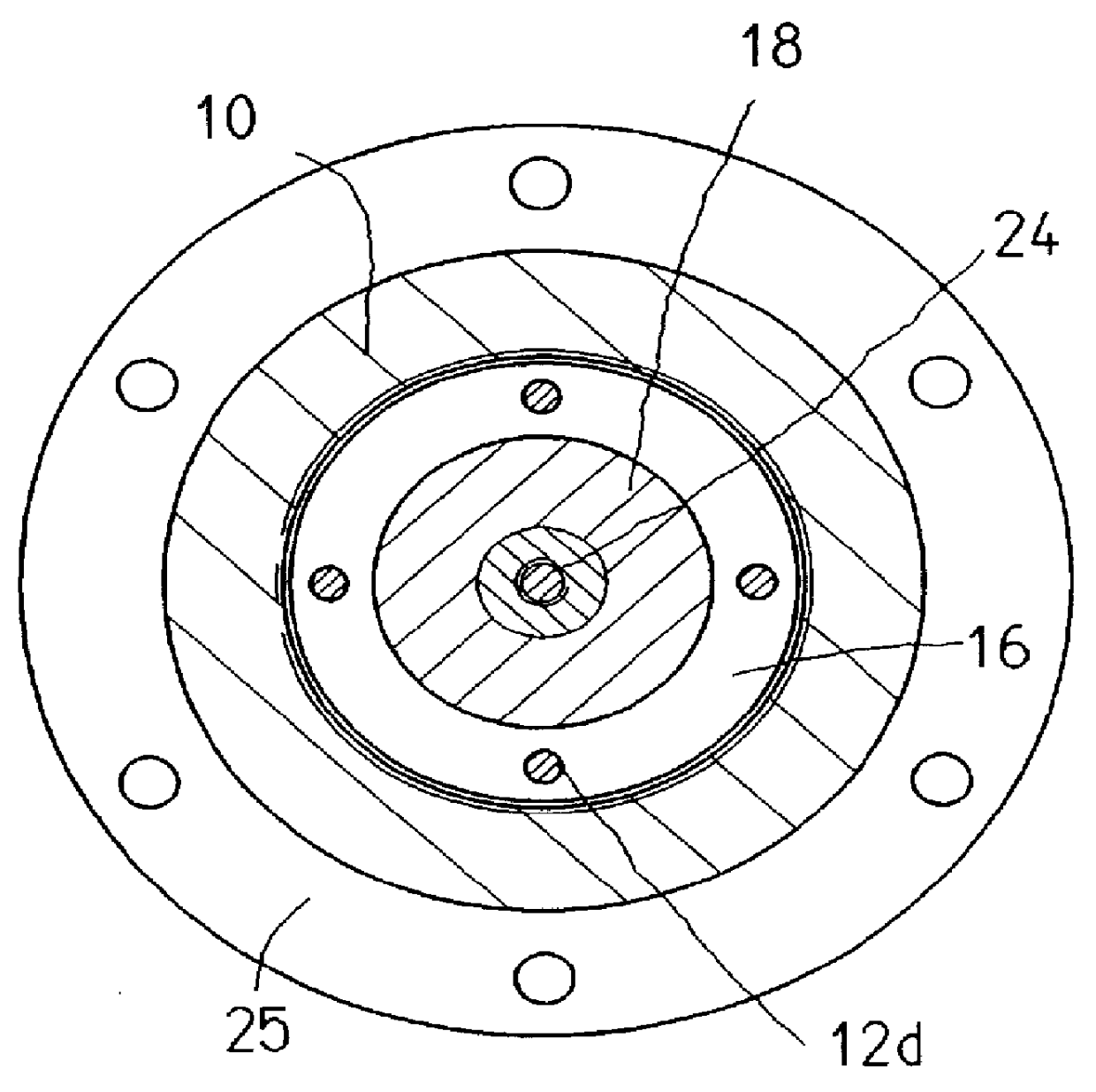
The embodiments show different devices for converting a rotary motion into an axial motion, which is frequently necessary in the field of electromechanical drives, in order to transfer the rotary motion of the motor into a translational motion. There are various applications for such devices. The device, for example, can be applied according to FIG. 6 to an injection molding machine for plastics as drive unit A. The drive units on the mold closing side, as well as those on the injection molding side, ejectors and the like, come into consideration as drive units. For example, the movable mold carrier 30 can be moved towards and away from the stationary mold carrier 31 by the drive represented on the bottom left side of FIG. 6, and the closing force is gener...


PUM

PropertyMeasurementUnit
Forceaaaaaaaaaa

Abstract

PCT No. PCT / DE96 / 02170 Sec. 371 Date May 13, 1998 Sec. 102(e) Date May 13, 1998 PCT Filed Nov. 12, 1996 PCT Pub. No. WO97 / 18406 PCT Pub. Date May 22, 1997A device for converting a rotary motion into an axial motion comprises an outer tube (10) with internal contours (10a), an inner shaft (11) with head (11a) with external contours (11b), an inner chamber (R) formed between tube (10) and shaft (11) and a plurality of roller elements (12) arranged in the inner chamber (R) and around the head (11a), which are in active engagement with at least one contour with the internal contour (10a) of the tube (10) and the external contour (11b) of the head (11a), whose position can be adjusted essentially by rotation relative to the roller elements (12). The shaft (11) is surrounded by a tubular element (14) arranged coaxially with respect to the central axis (a-a) of the shaft, which moves translationally relative to the tube (10) when the device is actuated. By this the device is protected in a most simple way from exterior influences: (FIG. 2).

Description

The present application claims the priority of German Patent Application 195 42 453, filed on Nov. 14, 1995, the disclosure of which is herewith also explicitly made the subject matter of the present application.The invention concerns a device for converting a rotary motion into an axial motion, the device including: an outer tube with internal contours; an inner shaft having a head including external contours, the inner shaft having a central axis; an inner chamber formed between the tube and the shaft; and several roller elements arranged in the inner chamber and around the head of the shaft, each roller element including at least one contour in active engagement with the internal contour of the tube and the external contour of the head, wherein the position of the head is axially adjustable essentially by rotation of the head relative to the roller elements.PRIOR ARTSuch a device is, for example, known from CH 290 685 within the meaning of a planetary-rolling-threaded-spindle dri...

Claims


Application Information

Patent Timeline
IPC IPC(8): B29C45/03B29C45/07B29C45/50B29C45/46F16H25/20F16H25/24
CPCB29C45/07B29C45/66F16H25/2228F16H25/2252B29C45/4005B29C45/5008B29C2045/1794Y10T74/19795F16H2025/2078Y10T74/19633Y10T74/18712B29C2045/5084
Inventor HEHL, KARL
Owner HEHL KARL
Why Eureka
Try Eureka