Apparatus for laser transmission welding, method for laser transmission welding, and a receptacle which is produced thereby and is closed by sheet

a technology of laser transmission welding and apparatus, which is applied in the direction of domestic applications, hollow objects, other domestic objects, etc., can solve the problems of increased shadowing, device is not intended, nor is it suitable, and the welding seam which connects the lid to the bottom part up to the outermost edge is no longer possible, and achieves low tolerance of wall structure. , the effect of high strength

Active Publication Date: 2017-05-30
JENOPTIK AUTOMATISIERUNGSTECHN
View PDF24 Cites 1 Cited by
  • Summary
  • Abstract
  • Description
  • Claims
  • Application Information

AI Technical Summary

Benefits of technology

[0015]It is the object of the invention to provide an apparatus which allows a sheet which is provided as a cover of a receptacle opening and which has a low sensitivity to tolerances of the wall structure to be welded to slender end faces of very thin wall structures of a receptacle and, in so doing, to achieve a weld seam with high strength.
[0016]A further object of the invention is to provide a method in which a sheet which is provided as a cover of a receptacle opening can be welded to very thin-walled wall structures of a receptacle with high strength.
[0017]A further object of the invention is to provide a receptacle which can be closed by sheet and in which a strength of the weld seam which is comparable or higher (compared to the prior art) can be achieved with minimal expenditure on material while improving the mechanical protection of the sheet closing a receptacle opening.

Problems solved by technology

A weld seam which connects the lid to the bottom part up to the outermost edge is thus no longer possible.
This device is disadvantageous in that, in order to introduce the pressing force, it requires a suitable, stable and, therefore, specially fabricated lid which must be exactly aligned and fitted on either manually or by handling devices.
The device is not intended, nor is it suitable, for handling a lid comprising thin sheet.
Attaching the pressing bodies by means of a corresponding quantity of connecting struts would require considerable effort and would inevitably either result in increased shadowing of the laser beam or the clamping device would be too unstable to transmit pressing forces.
However, because the sheet is tensioned in X direction and Y direction, the device described in the not-prior-published DE 10 2011 055 203.0 is only able to compensate for tolerances in the planarity of the end walls of the absorptive workpiece part to a limited extent.
However, it would be impossible to weld even thinner wall structures because if the end face were any smaller it would no longer be possible to achieve adequate strength in the weld seam.

Method used


Image

  • Apparatus for laser transmission welding, method for laser transmission welding, and a receptacle which is produced thereby and is closed by sheet
  • Apparatus for laser transmission welding, method for laser transmission welding, and a receptacle which is produced thereby and is closed by sheet
  • Apparatus for laser transmission welding, method for laser transmission welding, and a receptacle which is produced thereby and is closed by sheet

Examples


Embodiment Construction

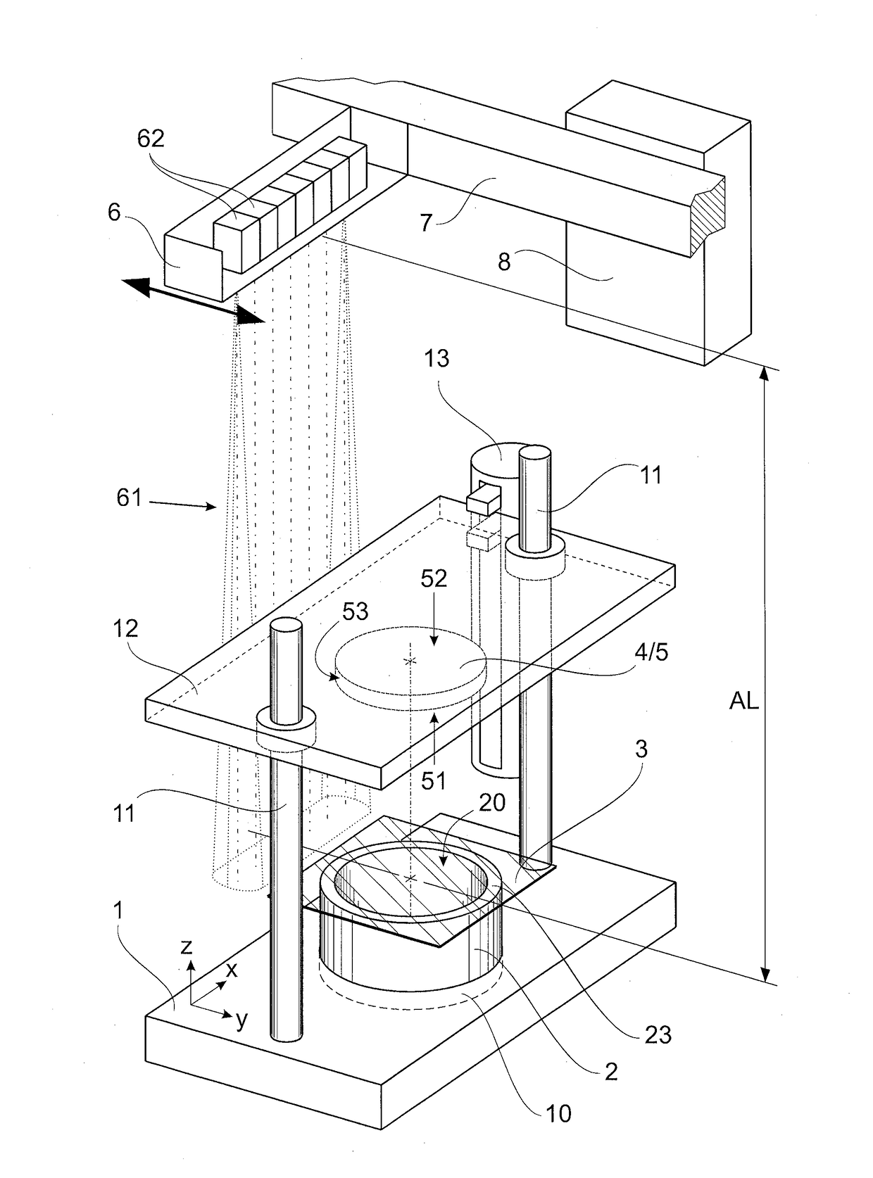
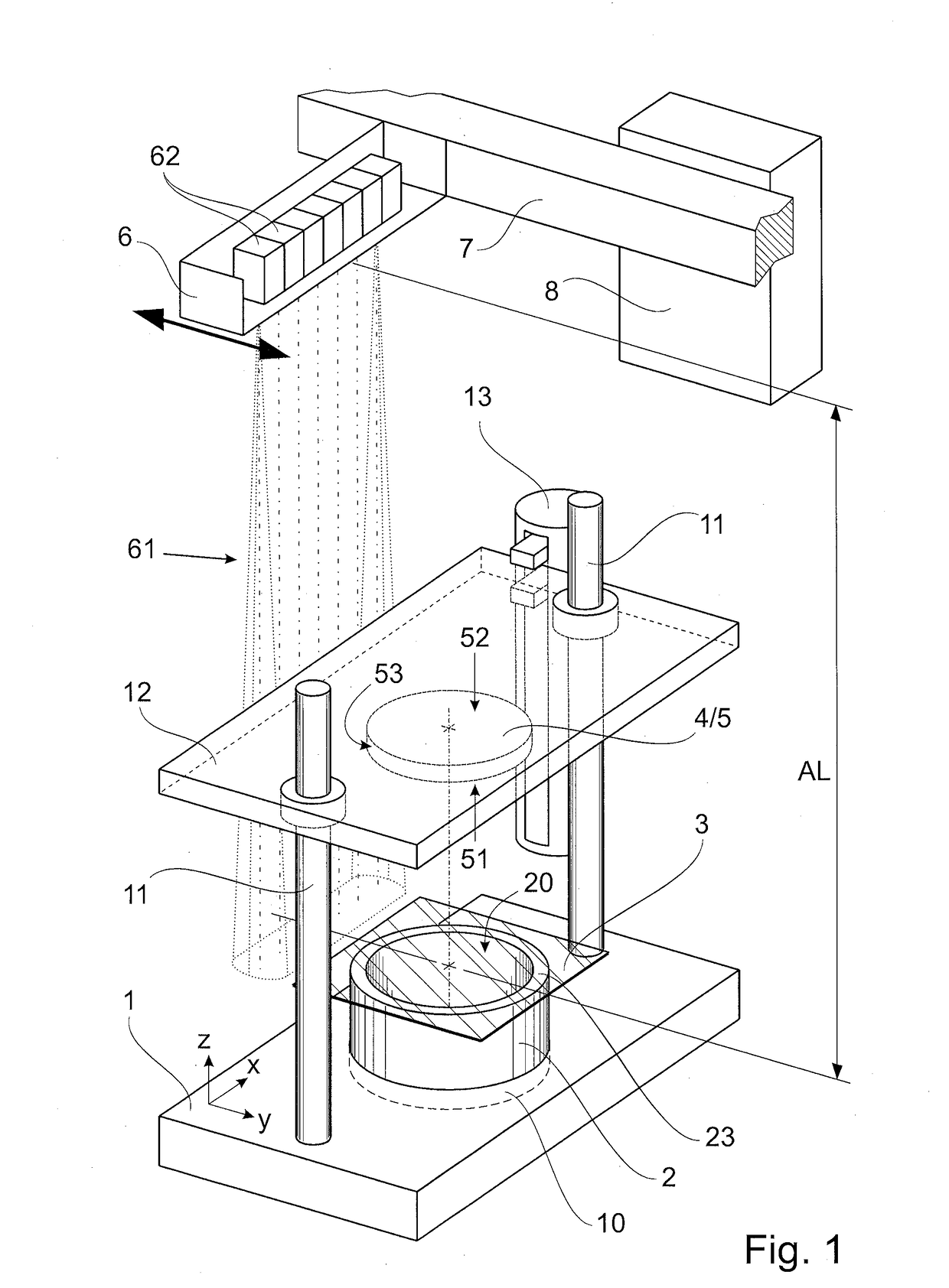
[0025]According to a first embodiment example shown in FIG. 1, an apparatus for laser transmission welding substantially has a holder 1, a laser radiation source 6, a movement device 7, a storage-and-control unit 8, and a carrier plate 12 with at least one pressing unit 4. The holder 1 is configured to position an open receptacle 2 in directions in perpendicular relationship to one another, i.e., the X direction, a Y direction and the Z direction, relative to a laser beam 61 which is directed to the holder 1 in Z direction and which proceeds from the laser radiation source 6. The laser radiation source 6 is arranged at the movement device 7 so as to be movable relative to the holder 1 in Y direction. The apparatus has a storage-and-control unit 8 for spatially resolved actuation of the laser radiation source 6 in X direction and Y direction and for controlling the movement device 7. The transparent carrier plate 12 is arranged between the holder 1 and the laser radiation source 6 an...


PUM

PropertyMeasurementUnit
wavelength rangeaaaaaaaaaa
heightaaaaaaaaaa

Abstract

A method for producing a receptacle which is closed by a sheet by transmission laser welding, and to an apparatus suitable to carry out same. The method and the apparatus are configured in such a way that a weld seam is formed between the wall structure of the receptacle and the sheet so as to be wider than the end faces of the wall structure.

Description

RELATED APPLICATIONS[0001]The present application claims priority benefit of German Application No. DE 10 2013 101 224.8 filed on Feb. 7, 2013, the contents of which are incorporated by reference in its entirety.FIELD OF THE INVENTION[0002]The invention is directed to an apparatus for laser transmission welding, a method for laser transmission welding and a receptacle which is produced thereby and is closed by a sheet.BACKGROUND OF THE INVENTION[0003]Generally, in laser transmission welding two workpiece parts are connected to one another. For this purpose, the two workpiece parts must directly contact in the joining region so that they can be welded. One of the workpiece parts is transmissive for the laser radiation and faces the laser source during welding. The other workpiece part is absorptive for the laser radiation. The laser beams penetrate the transmissive workpiece part and are converted into heat energy in the upper layers of the absorptive workpiece part. The upper layers...

Claims


Application Information

Patent Timeline
Patent Type & Authority Patents(United States)
IPC IPC(8): B29C65/16B65D25/04B21D51/26B29C65/78B29C65/00B29L22/00B29L31/00
CPCB65D25/04B29C65/16B29C65/1635B29C65/1654B29C65/1664B29C65/1674B29C66/118B29C66/242B29C66/24221B29C66/53461B29C66/73921B29C66/8322B21D51/2653B29C65/1616B29C65/1658B29C65/7858B29C66/112B29C66/114B29C66/1182B29C66/81268B29C66/8432B29K2995/0027B29L2022/007B29L2031/712B29C66/612
Inventor WOLLMANN, WERNERSTEINER, CHRISTOPHKRAEMER, WILFRIEDKRZYZANIAK, NORBERT
Owner JENOPTIK AUTOMATISIERUNGSTECHN
Why Eureka
Try Eureka