Strip line filter

Inactive Publication Date: 2010-04-15
MURATA MFG CO LTD
View PDF10 Cites 0 Cited by
  • Summary
  • Abstract
  • Description
  • Claims
  • Application Information

AI Technical Summary

Benefits of technology

[0019]According to the preferred embodiments of the present invention, since capacitance generated between the branch section and the second resonant line can be added to mutual capacitance, coupling between the re

Problems solved by technology

However, accuracy of shapes of electrodes is limited, and when the line widths ar

Method used


Image

  • Strip line filter
  • Strip line filter
  • Strip line filter

Examples


first embodiment

[0027]A strip line filter 1 will now be described.

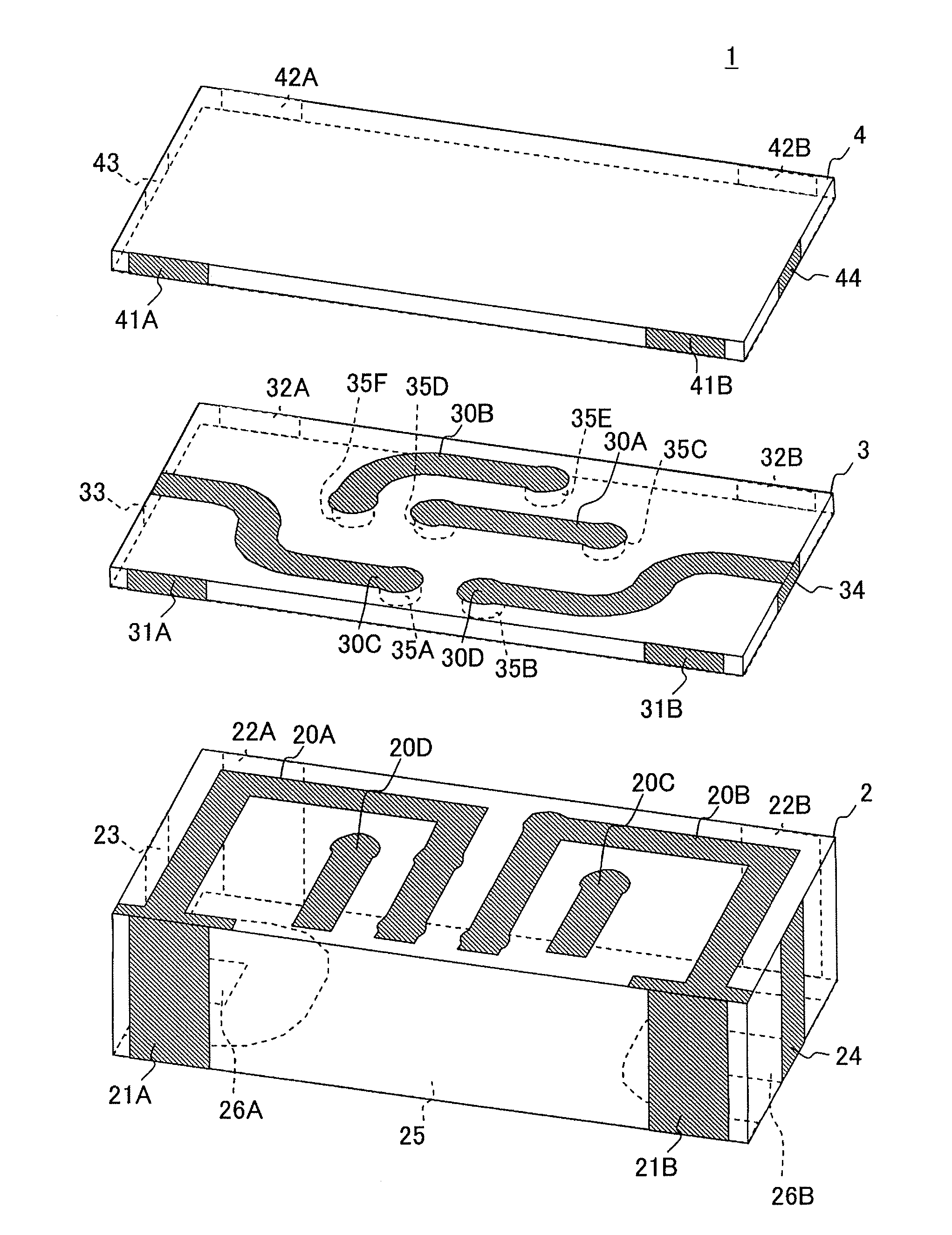
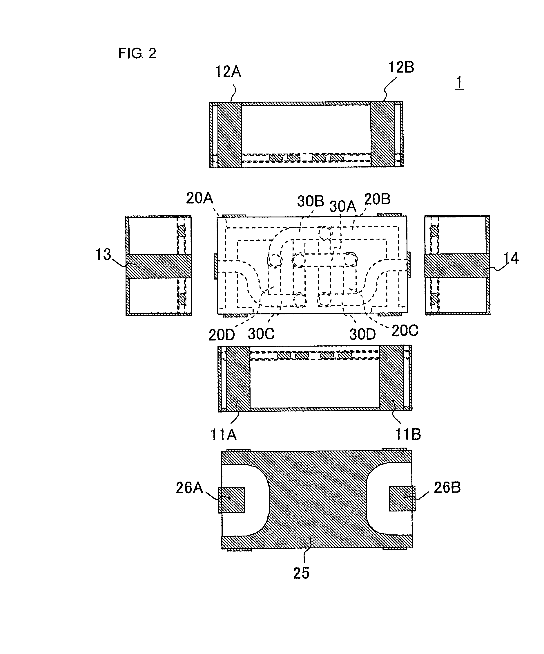
[0028]The strip line filter 1 of this embodiment is a band pass filter for high bands of UWB (Ultra Wide Band) communication. FIG. 2 is a development view illustrating the strip line filter 1 of this embodiment.

[0029]The strip line filter 1 includes side-surface lines 11A and 11B on a front surface thereof. On a back surface of the strip line filter 1, side-surface lines 12A and 12B are arranged. On a left surface, a side-surface line 13 is arranged. On a right surface, a side-surface line 14 is arranged. On a bottom surface serving as an implementing surface, a ground electrode 25 and input / output electrodes 26A and 26B are arranged. The ground electrode 25 and the input / output electrodes 26A and 26B are arranged separately from each other. When the strip line filter 1 is implemented on an implementing substrate, high-frequency-signal input / output terminals are connected to the input / output electrodes 26A and 26B, and a ground elec...

second embodiment

[0052]Next, a strip line filter 50 according to the present invention will be described.

[0053]FIG. 5 is a top plan view illustrating the strip line filter 50 of this embodiment. In the strip line filter 50, electrode patterns of a top surface of a substrate 2 and a top surface of a first glass layer 3 are different from those of first embodiment. Note that components the same as those shown in the first embodiment are denoted by reference numerals the same as those used in the first embodiment, and therefore, descriptions thereof are omitted.

[0054]On the top surface of the dielectric substrate 2, top-surface lines 52A to 52D included in resonators in two stages are arranged. The top-surface line 52A extends from a connection portion between the top-surface line 52A and a side-surface line 11A toward the center of a front surface of the dielectric substrate 2, and bends at a portion near the center of the front surface of the substrate 2 toward a back surface of the dielectric substr...

third embodiment

[0059]Next, a strip line filter 60 according to the present invention will be described.

[0060]FIG. 6 is a top plan view illustrating the strip line filter 60 of this embodiment. In the strip line filter 60, electrode patterns on a top surface of a dielectric substrate 2 and a top surface of a first glass layer 3 are different from the strip line filters of the first and second embodiments, and resonant lines are coupled with each other in an interdigital manner. Note that components the same as those shown in the first embodiment are denoted by reference numerals the same as those used in the first embodiment, and therefore, descriptions thereof are omitted.

[0061]On the top surface of the dielectric substrate 2, top-surface lines 62A to 62D included in resonators in two stages are arranged. The top-surface line 62A extends from a connection portion between the top-surface line 62A and a side-surface line 11A toward the center of a front surface of the dielectric substrate 2, and ben...


PUM


Abstract

A strip line filter includes a substantially rectangular plate-like shaped dielectric substrate. A ground electrode is arranged on a bottom surface of the substrate. A first resonant line and a second resonant line face the ground electrode through the substrate. Input/output electrodes are connected to the corresponding resonant lines. The first resonant line includes a first top-surface line, a connection line, and a second top-surface line. The first top-surface line is arranged on the top surface of the substrate and extends so as to pass a portion adjacent to a portion, on the left side, of a third top-surface line. The connection line and the second top-surface line are branched from the first top-surface line and pass a portion adjacent to a portion, on the right side, of the third top-surface line.

Description

BACKGROUND OF THE INVENTION[0001]1. Field of the Invention[0002]The present invention relates to a strip line filter including a dielectric substrate and strip lines arranged on the dielectric substrate.[0003]2. Description of the Related Art[0004]Strip line filters including strip-line resonators arranged on dielectric substrates have been used in various fields (refer to Japanese Unexamined Patent Application Publication No. 7-312503).[0005]Here, an example of an equivalent circuit of a conventional strip line filter will be described. FIG. 1 is a diagram illustrating an equivalent circuit of a conventional microstrip line filter 101 shown with reference to Japanese Unexamined Patent Application Publication No. 7-312503.[0006]The microstrip line filter 101 is configured such that ¼ wavelength strip line resonators in two stages are coupled with each other in a comb-line manner and the ¼ wavelength strip line resonators are externally coupled with respective input / output terminals ...

Claims


Application Information

Patent Timeline
IPC IPC(8): H01P3/08
CPCH01P1/20336
Inventor NAKAMURA, SOICHI
Owner MURATA MFG CO LTD
Why Eureka
Try Eureka