Method of detecting an ionization current

a technology of ionization current and detection method, which is applied in the direction of generator generated ignition energy, engine ignition, electric ignition installation, etc., can solve the problems of uncertainty in interpretation of measurements carried out, difficulty in handling generated voltage (up to about 50 kv) by means of commercially available electronic components, and influence of ionization current amplitude by gasoline additives

Inactive Publication Date: 2000-02-29
SEM AB
View PDF13 Cites 24 Cited by
  • Summary
  • Abstract
  • Description
  • Claims
  • Application Information

AI Technical Summary

Benefits of technology

is to generate an ionization current in the spark gap of an internal combustion engine and solve the problems mentioned above relating to the electronic components and the effect from the spark current. After signal processing, the detection of knock, misfire, combustion quality and so on can be accomplished by means of this ionization current. According to the invention, the ionization current is generated by applying a low voltage across the spark gap, which has to be done after the decay of the generated spark so that the spark does not disturb the measurement of the ionization current. The voltage is applied by means of an ignition magneto, for example a high frequency oscillator. It is known to arrange an ignition magneto in a capacitive ignition system in order to charge a charging capacitor. See our Swedish patent application No. 9501259-7. According to the invention, this ignition magneto is also used to generate said voltage for the purpose of generating an ionization current. The voltage is applied across the spark gap by means of the secondary coil of the ignition device or across a specially arranged winding. The ionization current generated is detected on the low tension side of the secondary side of the ignition device.

Problems solved by technology

On the high tension side, a measurement problem is the difficulty of handling the generated voltage (up to about 50 kV) by means of commercially available electronic components.
According to this method there are problems as well, that is to say component tolerance problems and leakage currents coming into existence in components and coils and causing interpretation uncertainty of the measurements carried out.
Furthermore, the spark itself disturbs the measurements of the ionization current when the spark current and ionization current are time-connected to each other, and the differences of the amplitudes are about 1000 times. Another problem is that the ionization current amplitude is influenced by gasoline additives.

Method used


Image

  • Method of detecting an ionization current
  • Method of detecting an ionization current

Examples


Embodiment Construction

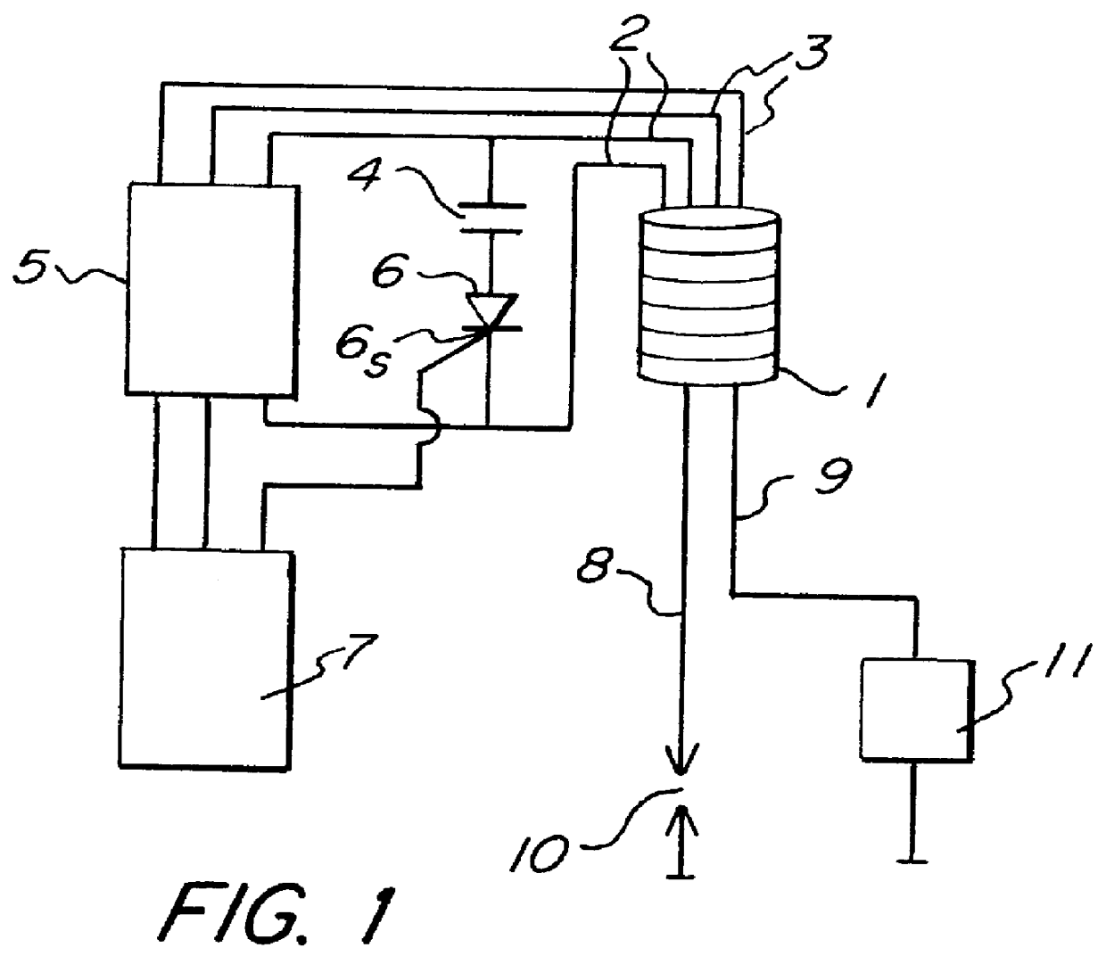
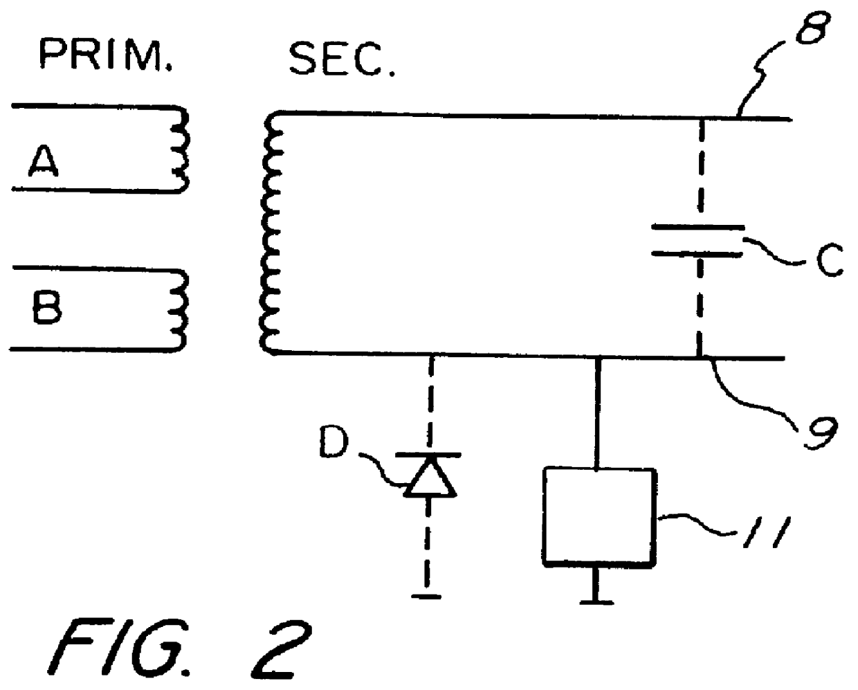
FIG. 1 indicates a capacitive ignition system of an internal combustion engine. The invention can also be used in inductive ignition systems. 1 indicates an ignition coil with a connection 2 to a first primary winding A and a connection 3 to a second primary winding B, which is arranged specially for said purpose. A charging capacitor 4, preferably having a low capacity, is connected to the connection 2 of the first primary winding. A The charging capacitor 4 is also connected to an ignition magneto 5, for example a high frequency oscillator, in order to give a short high energy spark being able to ignite the fuel mixture. The connection 3 of the second primary winding B is connected to high frequency oscillator 5 to make it possible also to use the high frequency oscillator 5 as a low tension source for the generation of the ionization current. The discharge of the charging capacitor 4 is controlled by a thyristor 6 or the like, the control electrode 6.sub.s of which is connected t...


PUM


Abstract

PCT No. PCT/SE97/01022 Sec. 371 Date Dec. 10, 1998 Sec. 102(e) Date Dec. 10, 1998 PCT Filed Jun. 11, 1997 PCT Pub. No. WO97/47875 PCT Pub. Date Dec. 18, 1997A method for generation of a low test voltage is used for the purpose of detecting an ionization current in the spark gap of an internal combustion engine. The voltage is generated by a controllable ignition magneto (5) arranged in order to charge (2) an ignition capacitor (4). The voltage is applied (3) to the primary side of the ignition device after generation of a spark and after the decay of the spark, after which the ionization current is detected (11) on the secondary side of the ignition device.

Description

1. Technical FieldThe present invention relates to a method for the generation of a voltage for the purpose of detecting an ionization current in the spark gap of an internal combustion engine. The detection is supposed to take place after the ignition of the spark and after the decay of the spark.2. Description of the Prior ArtIt is known that the combustion of an air / fuel mixture in an internal combustion engine results in the production of ions. These ions can be detected by applying a voltage across the spark gap with the result that an ionization current is generated. This ionization current can be measured and used for the detection of misfire, knock, missing combustion, combustion quality and so on, of the engine.The measurement of the ionization current attained in the spark gap can take place either on the high tension side of the spark device or on the low tension side.On the high tension side, a measurement problem is the difficulty of handling the generated voltage (up t...

Claims


Application Information

Patent Timeline
Patent Type & Authority Patents(United States)
IPC IPC(8): F02P17/12F02D45/00G01M15/04
CPCF02P17/12
Inventor BENGTSSON, JORGENOTTOSSON, LARS-OLOF
Owner SEM AB
Why Eureka
Try Eureka