
Ion source frequency feedback device and method

a technology of ion source frequency feedback and feedback device, which is applied in the direction of instruments, particle separator tube details, separation processes, etc., can solve the problems of low signal measurement reproducibility, high degree of non-specific “chemical noise” of the mass spectrum, and fluctuation in total ion current, so as to control the ionization efficiency

Inactive Publication Date: 2008-05-13
AGILENT TECH INC
View PDF7 Cites 7 Cited by
  • Summary
  • Abstract
  • Description
  • Claims
  • Application Information

AI Technical Summary

Benefits of technology

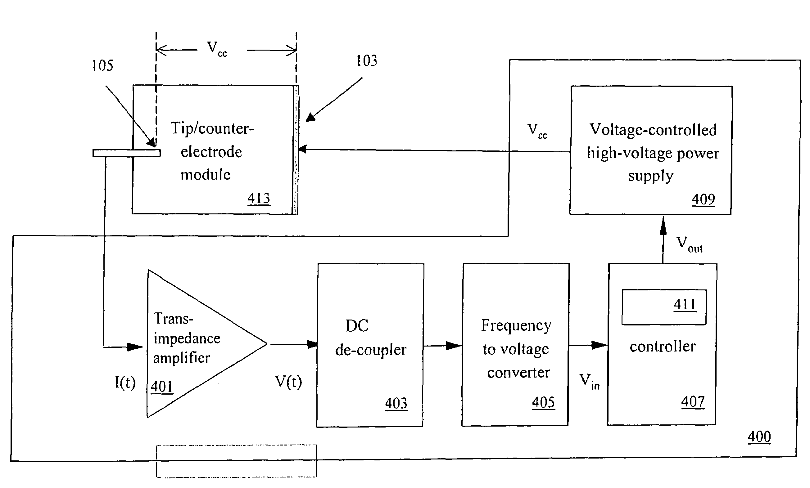
[0008]An ion source for controlling ion spray is described. The ion source comprises a capillary tip; a counter-electrode comprising an aperture for receiving ions ejected from the capillary tip; and a closed feedback loop for coupling the capillary tip to the counter-electrode and regulating a spray of ions ejected from the capillary tip. The closed feedback loop maintains ionization efficiency by measuring a modulation frequency of ionization currents and adjusting a tip to counter-electrode voltage.

Problems solved by technology

The pulsating mode generally produces droplets of a large distribution in size and charge, which cause fluctuation in total ion current and yield a high degree of non-specific “chemical noise” to the mass spectrum.
The pulsating mode also exhibits a pulsing behavior that creates poor reproducibility in signal measurement.
The multi-jet mode, however, is undesirable because at such high fields there is a potential for arcing between the tip and counter-electrode.
The method, however, requires constant operator attention and adjustment, and does not respond to varying conditions unless the operator observes and reacts to such changing conditions.
This feedback control system, however, requires large, expensive, and delicate optical instruments for image capture and analysis.

Method used


Image

  • Ion source frequency feedback device and method
  • Ion source frequency feedback device and method
  • Ion source frequency feedback device and method

Examples


Embodiment Construction

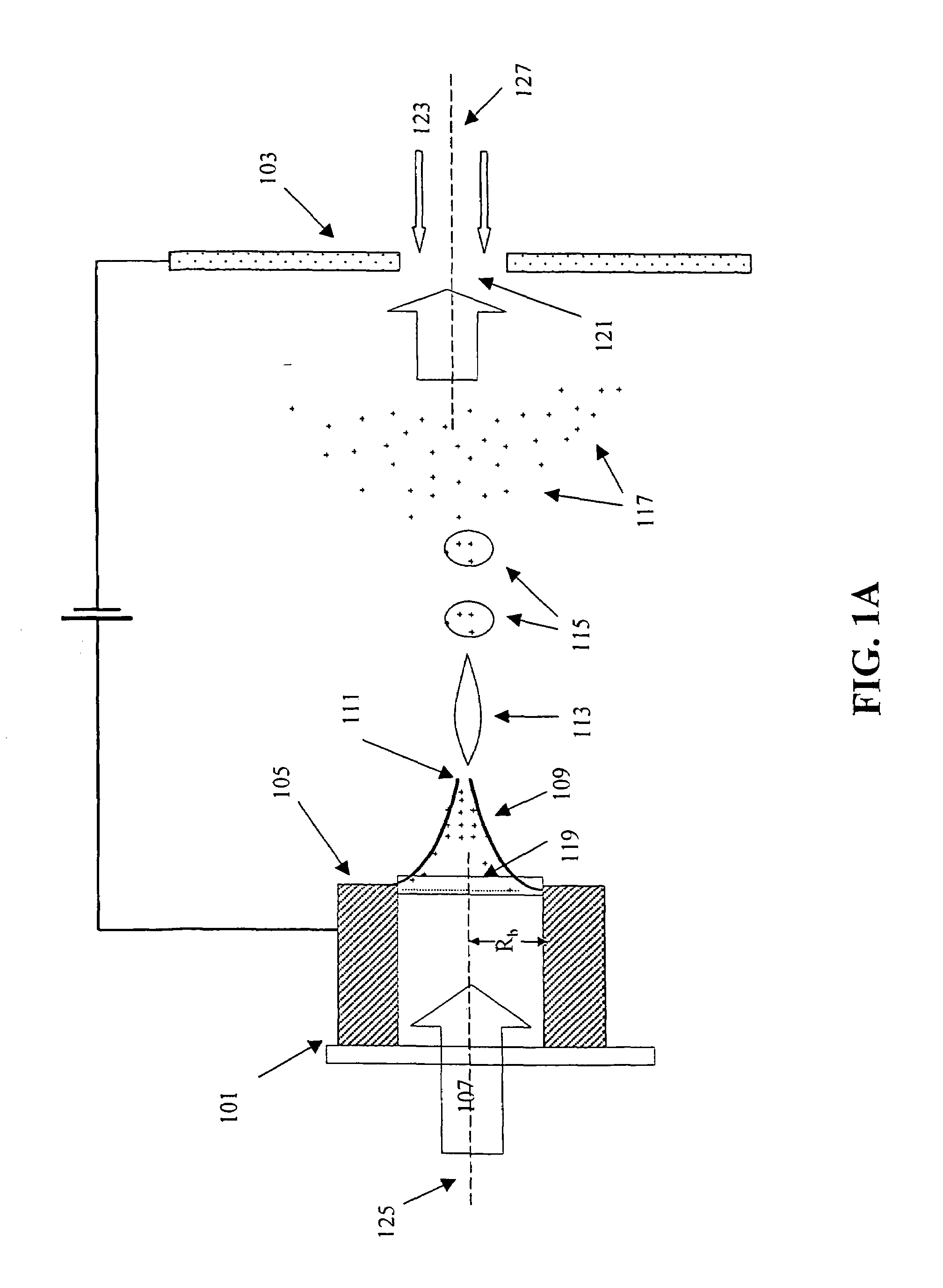
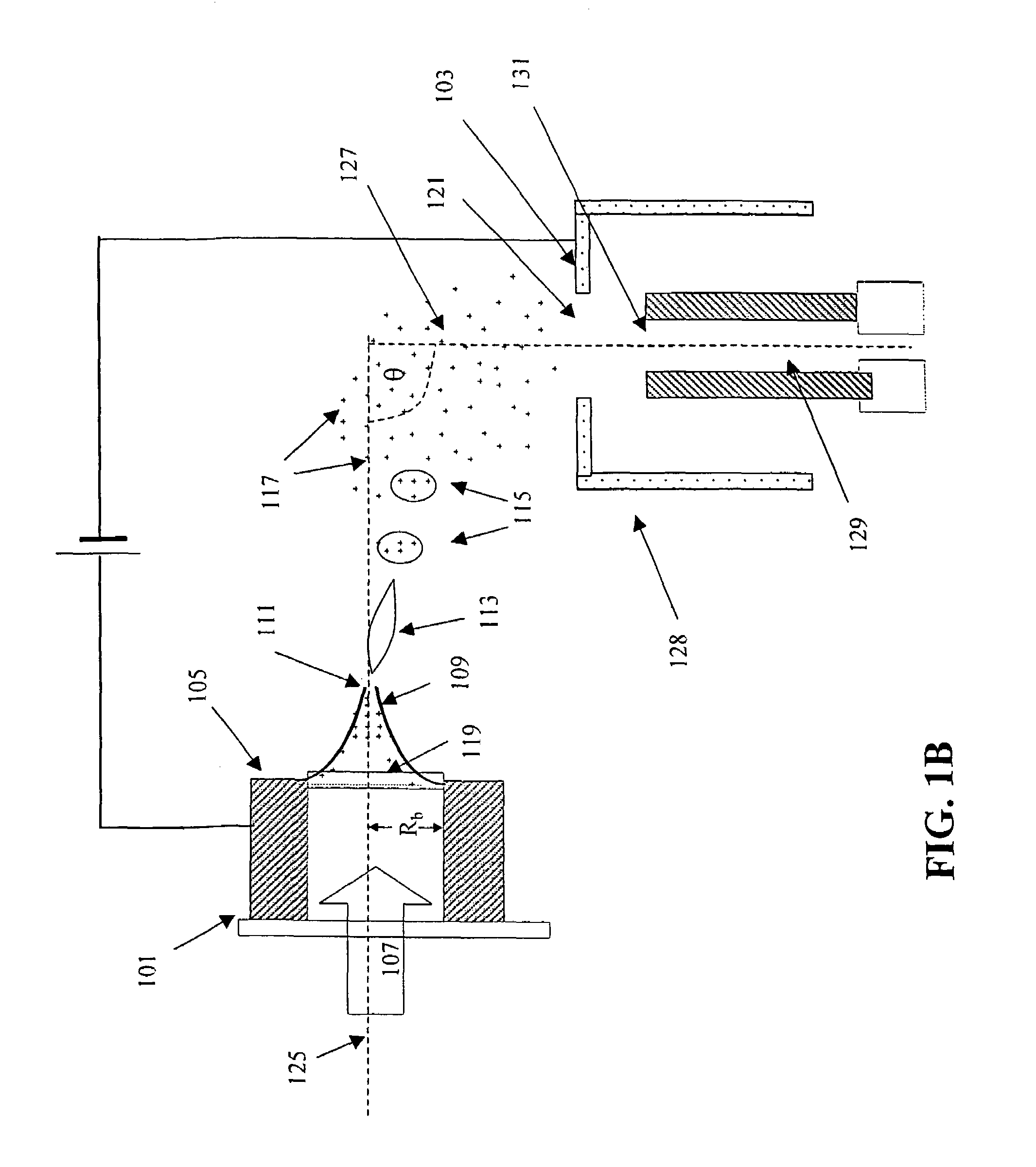
[0017]FIG. 1 is a schematic representation of an ionization process. As shown in FIG. 1, the placement of a capillary 101 in the vicinity of a counter-electrode 103 at high negative bias creates an electric field gradient at a capillary tip 105 of the capillary 101. A sample fluid 107 flowing through the capillary 101 exits out of the capillary 101 at the capillary tip 105. The jump in displacement flux density at the liquid-gas interface generates a surface charge, which in turn pulls the sample fluid 107 towards the counter-electrode 103. The combined electro-hydrodynamic force on the sample fluid 107 is balanced by the surface tension of the sample fluid 107, effectively creating a Taylor cone 109 having a base 119 and a tip 111. The tip 111 of the Taylor cone 109 extends into a micron-size filament 113. Moving downstream from the filament 113, interfacial forces from surface tension and charge repulsion coupled with small perturbations result in the breakup of the filament 113 a...


PUM


Abstract

An ion source for an analytical instrument is described. The ion source comprises a capillary tip and counter-electrode interface and a feedback loop control device connected to the capillary tip and counter-electrode interface. The feedback loop control device comprises a transimpedance amplifier, a DC de-coupler, a frequency to voltage converter, a controller, and a voltage-controlled high-voltage power supply that provides a tip to counter-electrode voltage to the capillary tip and counter-electrode interface. The feedback loop control device measures the modulation frequency of ionization currents and provides a feedback adjustment of the tip-to-counter-electrode voltage to maintain ionization efficiency.

Description

CROSS REFERENCE TO RELATED APPLICATION(S) [0001]This is a continuation of Ser. No. 10 / 896,981, filed on Jul. 23, 2004, now U.S. Pat. No. 7,022,982 entitled “ION SOURCE FREQUENCY FEEDBACK DEVICE AND METHOD,” the entire disclosure of which is incorporated into this application by reference. This application also claims priority of provisional application No. 60 / 543,542, filed Feb. 12, 2004, entitled “MASS-SPECTROMETER SIGNAL OPTIMIZATION EMPLOYING ELECTROSPRAY FREQUENCY FEEDBACK,” of which the subject matter is herein incorporated by reference in its entirety.TECHNICAL FIELD[0002]The technical field is analytical instruments and, in particular, signal optimization for mass spectrometers.BACKGROUND[0003]Electrospray ionization (ESI) is a technique for transporting bio-molecules diluted in a liquid into a gaseous phase. This desolvation method is customarily used for mass-spectrometry identification of proteins. For example, protoleolytic enzymes are employed to digest proteins into uni...

Claims


Application Information

Patent Timeline
IPC IPC(8): H01J49/10H01J27/02H01J49/04H01J49/16
CPCH01J49/165
Inventor SOBEK, DANIELCAI, JINGKILLEEN, KEVINYIN, HONGFENG
Owner AGILENT TECH INC
Learn More