Method for controlling drives of conveying machinery

a technology of conveying machinery and drives, which is applied in the direction of control devices for conveying machines, conveyor parts, transportation and packaging, etc., can solve the problems of affecting the operation of the conveying machine, the tension required for the lower strand is greater than the tension required, and the chain and/or the machine frame are severely damaged

Inactive Publication Date: 2000-02-29
CATERPILLER GLOBAL MINING EURO GMBH
View PDF6 Cites 31 Cited by
  • Summary
  • Abstract
  • Description
  • Claims
  • Application Information

AI Technical Summary

Benefits of technology

An object of the invention is to provide a method for controlling such conveying machinery by which chain sag at the main drive of conveyor machinery can reliably be avoided.
The invention proposes controlling the drives as a function of the loading of the conveyor in such a way that in the low load range of the conveyor a higher output is produced by the auxiliary drive(s) than the main drive(s) and, as the loading of the conveyor increases, the output advantage of the auxiliary drive(s) relative to the main drive(s) is reduced.
By means of the method according to the invention the critical situation of chain sag at the main drive can be reliably prevented or at least mitigated on any conveyor by virtue of the fact that in the low load range, where greater tension is required for the lower strand than for the upper, the auxiliary drive receives a higher output than all the main drives combined, thus ensuring that the auxiliary drive alone exerts the necessary tension on the lower strand and in so doing is not assisted by the main drive(s), which would otherwise result in chain sag at the main drive. Instead, the load distribution in the low load range is chosen so that the auxiliary drive carries a sufficiently large proportion of the total load to be able to exert, via the wrap of the chain at the main drive, part of the tension required for the upper strand. This ensures that chain sag (if it occurs at all) can only form at the auxiliary drive, that is to say on the exposed top side of the conveyor, where adequate room is available for the slack region of the chain, and no damage is caused to chain and / or conveyor.

Problems solved by technology

Owing to their construction, the scraper chain conveyors used in underground coal mining are subject to "chain sag" involving a slackening of the chain in the region of the main drive and / or auxiliary drive after the chain has passed round the sprocket wheel.
At the auxiliary drive the sag occurs on the open, exposed upper side of the conveyor, where the untensioned slack portion of the chain is unconfined, so that sag in this region of the conveyor seldom causes any problems.
At the main drive, however, sag occurs in the concealed lower part of the main drive machine frame, where clearances are limited, so that the slack may cause jamming and severe damage to the chain and / or to the machine frame.
However, if the conveyor is running under no load or under low load, the tension required for the lower strand is greater than the tension required for the upper strand, since the lower strand is subject to increased friction due to small coal and dirt which accumulates in the lower part of the machine frame.
The consequence is that, even with driving output symmetrically divided between the main and auxiliary drives, sag will occur first at the main drive, where it may be unnoticed and may quickly lead to severe damage to the conveyor.
If the conveyor is provided with more main drives than auxiliary drives, and all drives receive the same output, the risk of sag at the main drives is even greater.

Method used


Image

  • Method for controlling drives of conveying machinery
  • Method for controlling drives of conveying machinery

Examples


Embodiment Construction

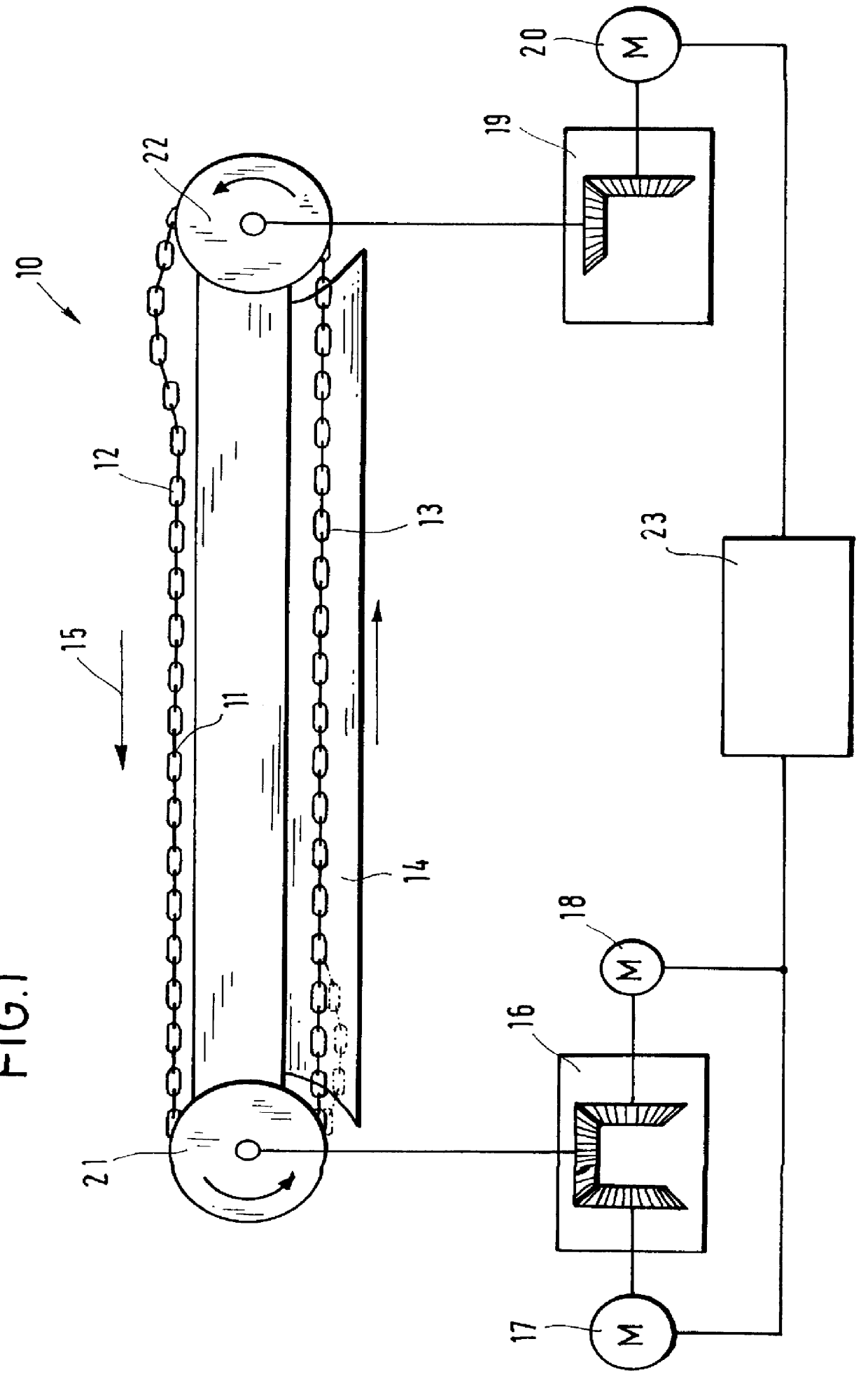
FIG. 1 is a highly diagrammatic illustration showing a scraper chain conveyor 10 for an underground mining operation, with an endless chain 11 which is provided with scrapers (not shown). The upper strand 12 of the chain 11 runs inside an upwardly open conveyor trough assembled from a plurality of trough sections, whilst the lower strand 13 is led back through an enclosed passage 14 on the machine frame. Coal cut by a machine falls into the upwardly open trough of the scraper chain conveyor 10 and is transported in the direction of the arrow 15 by the scrapers on the upper strand 12.

The drive system of the conveyor 10 comprises a main drive station 16 with two main drive motors 17, 18 and an auxiliary drive station 19 with one auxiliary drive motor 20. The main drive station 16 drives a first chain sprocket 21 which directly sustains the load exerted by the upper strand 12 due to coal being conveyed, while the auxiliary drive station drives a second chain sprocket 22 which pulls the...


PUM


Abstract

A method for controlling the main and auxiliary drives of conveyors, for example, in underground mining. The drives are controlled as a function of the loading of the conveyor in such a way that in a low load range of the conveyor the auxiliary drive produces a higher output (20I) than the main drives and as the load increases the output advantage of the auxiliary drive in relation to the main drives is reduced. This special load distribution to auxiliary and main drives has the advantage that sagging of the conveyor element, for example the chain of a scraper chain conveyor in the inaccessible and concealed lower strand, close to the main drive, can be prevented. The risk of damage to the machine frame or conveyor chain is thereby reduced.

Description

The invention relates to a method for controlling drives, in particular main drives and auxiliary drives, of conveying machinery. The method of the invention is especially, although not necessarily exclusively, useful in underground mining, particularly for controlling scraper chain conveyors as commonly used for conveying coal.BACKGROUND OF INVENTIONOwing to their construction, the scraper chain conveyors used in underground coal mining are subject to "chain sag" involving a slackening of the chain in the region of the main drive and / or auxiliary drive after the chain has passed round the sprocket wheel. The sag is due partly to the fact that the conveyors are constructed in individual segments, which necessitates a certain amount of play in the chain, and partly to elongation of the chain during its operating life, and variations in the length of the conveyor itself.At the auxiliary drive the sag occurs on the open, exposed upper side of the conveyor, where the untensioned slack p...

Claims


Application Information

Patent Timeline
Patent Type & Authority Patents(United States)
IPC IPC(8): B65G23/36B65G23/00
CPCB65G23/36
Inventor WEIGEL, WILFRIEDBREIMHORST, ARNOTITSCHERT, JENS
Owner CATERPILLER GLOBAL MINING EURO GMBH
Why Eureka
Try Eureka