Electronic bankbook and processing system for financial transaction information using electronic bankbook

Inactive Publication Date: 2000-02-29
N T T DATA TSUSHIN KK
View PDF25 Cites 203 Cited by
  • Summary
  • Abstract
  • Description
  • Claims
  • Application Information

AI Technical Summary

Benefits of technology

As a result, the burden of danger upon the payer cannot exceed the set money amount which he has set in the beginning. On the other hand, it is very convenient from the point of view of the payment deputy, because it is not necessary ever to use cash, since it is possible to issue electronic checks with face values which match the amounts for payment on a case by case basis, provided that they are within the range of the usable money amount.
In the case that the additional rewrite restricti

Problems solved by technology

However, since a considerable cost is entailed when producing these cards, paper bankbooks, and transaction slips, the burden of expense to the banks is immense.
On the other hand, for the customers as well, carrying a plurality of cards, paper bankbooks, and the like becomes inconvenient from the management point of view.
As described above, in the conversion from paper bankbooks to electronic cards, the implementation of the combination together of the functions of several cards has been extremely difficult, even independently of the fact that the demands of society are high, due to the existence of problems such as those described below, mainly in the way in which the detailed bankbook information should be recorded upon the cards.
but the down side is that the recording capacity of low cost cards is insufficient even for just simply recording the detailed bankbook information, and high capacity cards have the defect that the production cost becomes high.
As described above, when considering the point that it should be impossible to tamper with the detailed bankbook information (which must not be done) and also the point that it is necessa

Method used


Image

  • Electronic bankbook and processing system for financial transaction information using electronic bankbook
  • Electronic bankbook and processing system for financial transaction information using electronic bankbook
  • Electronic bankbook and processing system for financial transaction information using electronic bankbook

Examples


Embodiment Construction

The Basic Construction of the Electronic Bankbook

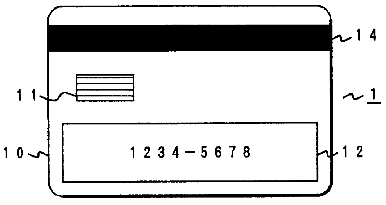
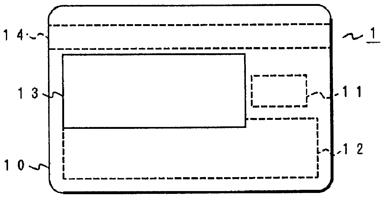
FIG. 1(a) is a front view of an electronic bankbook according to one embodiment of the present invention, and FIG. 1(b) is a rear view thereof. In this electronic bankbook 1, an IC chip 11 is disposed in a region which is between an embossment 12 of a card base board 10 made of resin and a magnetic stripe 14, and which is to the left side of the card base board 10 when the magnetic stripe 14 is at the top thereof. An optical recording medium 13 is disposed upon the generally central section of the rear of the card base board 10, that is to say in a position which avoids the rear sides of the IC chip 11, the inscribed portion of the embossment 12, and the magnetic stripe 14.

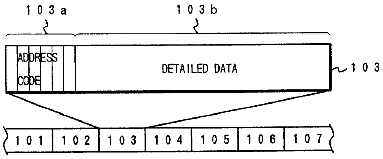
The IC chip 11 is, for example, a conventional S type chip for IC card use which has a CPU and a semiconductor memory such as an EEPROM or the like, and in this semiconductor memory there is provided a search key information storage regions for storing payee informa...


PUM


Abstract

PCT No. PCT/JP95/01427 Sec. 371 Date Mar. 18, 1996 Sec. 102(e) Date Mar. 18, 1996 PCT Filed Jul. 18, 1995 PCT Pub. No. WO96/02890 PCT Pub. Date Feb. 1, 1996The object of the present invention is to propose an account bankbook, a money transfer card, a receipt file, and a checkbook utilizing an optical card, an IC card, or a hybrid optical/IC card. On the surface of a resin card base board 1 are formed an IC chip 11, an optical recording sheet 13, a magnetic stripe 14, and an embossment 12. In a semiconductor memory within the IC chip 11 are written validation keys, search keys, payee information, the upper limit amount of a check, and a program for processing transaction data. Access restrictions corresponding to various applications are imposed upon these data. The history of various cash transactions is recorded in the optical recording sheet 13. These records are of write-once type and rewriting or deletion thereof is impossible.

Description

The present invention relates to an electronic bankbook which combines on the same resin base board an IC card, an optical storage medium, and a magnetic stripe and embossing, and which has the functions of a money transfer card, a cash card, and a deposit account bankbook; and which further provides added value by combining these functions. And, in addition, the present invention also relates to a system which processes financial transaction information using an electronic bankbook.The computerization of financial work has progressed in recent years, and the demand is increasing for conversion from the paper bankbooks which are used in banks to electronic cards. IC cards and optical cards are proposed as cards which can correspond to these sorts of demands. IC cards, as is known, are ones in which IC chips including semiconductor memory are arranged in predetermined regions upon a card base board made of resin, and they combine both high security characteristics and also potential ...

Claims


Application Information

Patent Timeline
IPC IPC(8): G07F7/10G06K19/08G06K19/10
CPCG06K19/08G06K19/10G06Q20/341G06Q20/3415G06Q20/4093G07F7/1008
Inventor FURUHASHI, NOBUOINOUE, KENICHIROTAKEDA, TOMOOTAKAHASHI, SIGEFUMITOKUMASU, ATSUMIKOBAYASHI, TAKAFUMIIWASE, NORIYUKI
Owner N T T DATA TSUSHIN KK
Why Eureka
Try Eureka