Side-gored bag having a first zipper tape with an area of increased thickness and with an area of progressively reduced thickness

a zipper tape and bag technology, applied in the field of side-gored bags, can solve the problems of inability to accurately disperse a quantity, difficulty in process control, and limited loading capacity of bags of this typ

Inactive Publication Date: 2000-02-29
MEIWA PAX
View PDF14 Cites 54 Cited by
  • Summary
  • Abstract
  • Description
  • Claims
  • Application Information

AI Technical Summary

Problems solved by technology

However, any bag of this kind is limited in loading capacity because the lateral sides and bottom of an assembly of two panels are simply sealed.
In the process for manufacturing a zippered synthetic resin bag according to JP Koho H6-28921, the male and female ribs on the two (upper and lower) panel films must be disengaged and re-engaged during the fabrication process so that process control is difficult.
Moreover, since the product bag has only a narrow opening, the spoon used for taking out the contents, such as powdered milk, cacao, or the like, for instance, tends to get caught by the edge of the opening to cause a failure to dispense out an accurate quantity.

Method used


Image

  • Side-gored bag having a first zipper tape with an area of increased thickness and with an area of progressively reduced thickness
  • Side-gored bag having a first zipper tape with an area of increased thickness and with an area of progressively reduced thickness
  • Side-gored bag having a first zipper tape with an area of increased thickness and with an area of progressively reduced thickness

Examples


example 2

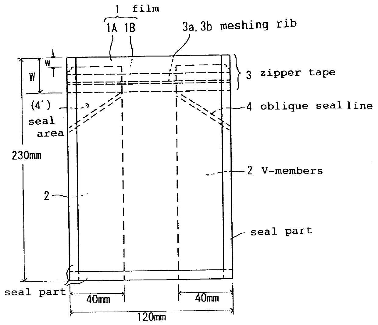
FIG. 4 is a front view showing an example of the side-gored bag according to the invention.

The side-gored bag of Example 2 is substantially identical to the bag of Example 1 but the area above the opening was also sealed and provided with a tear notch.

example 3

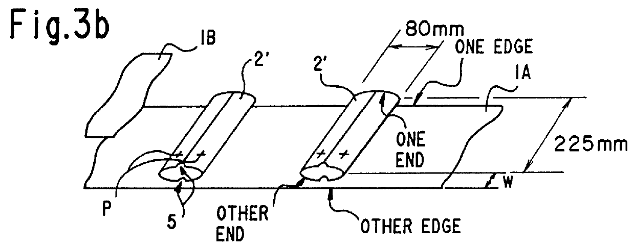
FIG. 5 is a perspective view showing another example of the collapsed cylindrical film strip 2'.

For use as the collapsed cylindrical film strip 2' to be positioned on a platform and fed intermittently in a transverse direction onto the first film 1A, the same material film as the one used in Example 1 was folded back from both sides into the shape of a collapsed cylinder and the abutted edges were fixed in position with a narrow heat-sealable tape t (a laminate tape of the linear low-density polyethylene layer / bi-axially oriented polyester film / linear low-density polyethylene layer construction). Otherwise, the procedure of Example 1 was repeated. However, in cutting the collapsed cylindrical film strip 2' transversely along its centerline in the final stage, decorative trimming involving an area slightly broader than the width of the heat-sealable tape t was used so that no residue of the heat-sealable tape t would appear on cut section.

When the abutted edges of the collapsed cylin...

example 4

FIG. 6 is a perspective view showing still another example of the collapsed cylindrical film strip 2' of the invention.

For use as the collapsed cylindrical film strip 2' to be positioned on a platform and fed intermittently in a transverse direction onto the first panel film 1A, the same material film as used in Example 1 was folded back from both sides into the shape of a collapsed cylinder and the abutted edges were bonded together with a hot-melt adhesive h. Otherwise, the procedure of Example 1 was repeated. However, in cutting the collapsed cylindrical film strip 2' transversely along its centerline in the final stage, decorative trimming involving an area slightly broader than-the width of the bonded area was carried out so that no residue of the bond formed with the hot-melt adhesive remained on cross section.


PUM

PropertyMeasurementUnit
thicknessaaaaaaaaaa
thicknessaaaaaaaaaa
widthaaaaaaaaaa

Abstract

A side-gored bag is provided which includes: a first panel film, a second panel film; a pair of V-members forming side gussets; and a zipper device including a first zipper tape, and a second zipper tape. The upper edges of the V-members are situated so as to be downwardly displaced by a distance w from the upper edges of the first and second panel films. The first zipper tape has a first meshing rib and the first zipper tape is bonded in a horizontal position to the first panel film over an area of the panel film which extends by a distance W (wherein W>w) from the upper edge in such a manner that both the lower side of the zipper tape and the first meshing rib are situated below the upper edges of the V-members so as to cover an upper part of each V-member. The second zipper tape has a second meshing rib and the second zipper tape is bonded to the second panel film in such a manner that the second meshing rib is aligned with the first meshing rib. The side-gored bag also includes an area adjacent to the upper side of the first zipper tape, which is of an increased thickness as compared with a remaining area of the tape, and an area adjacent to the lower side of the first zipper tape, which is progressively reduced in thickness toward the lower side.

Description

The present invention relates to a side-gored bag provided with a V-shaped gusset or gore along either lateral side and a zipper device along its opening and to a process for manufacturing the side-gored bag. The term "zipper device" is used herein to mean a fastener device consisting of a tape having a male rib and a fellow tape having a female rib.BRIEF DESCRIPTION OF THE PRIOR ARTA bag equipped with a zipper device along its opening is well known. However, any bag of this kind is limited in loading capacity because the lateral sides and bottom of an assembly of two panels are simply sealed.To overcome this disadvantage, several versions of a bag provided with a gusset along either side and a fastener means along its opening have been proposed and some of them are already on the market.For example, Japanese Patent (JP) Koho H6-28921 (JP Kokai S63-17036) discloses a process for manufacturing a zippered plastic bag which comprises a step of feeding two (upper and lower) panel films ...

Claims


Application Information

Patent Timeline
Patent Type & Authority Patents(United States)
IPC IPC(8): B65D33/25B65D30/10B65D30/20B65D30/16B31B1/90
CPCB65D31/10B65D33/2533B65D33/2541Y10T24/45168Y10S24/40B65D33/2508B65D75/527
Inventor MITARAI, MOTOSHI
Owner MEIWA PAX
Why Eureka
Try Eureka