Double resonant wideband patch antenna and method of forming same

a patch antenna and double resonant technology, applied in the field of antennas, can solve the problems of narrow bandwidth and limit the application of the patch antenna

Inactive Publication Date: 2000-03-07
MOTOROLA INC
View PDF1 Cites 72 Cited by
  • Summary
  • Abstract
  • Description
  • Claims
  • Application Information

AI Technical Summary

Problems solved by technology

One problem associated with the patch antenna is its narrow bandwidth.
Practically speaking at such high f

Method used


Image

  • Double resonant wideband patch antenna and method of forming same
  • Double resonant wideband patch antenna and method of forming same
  • Double resonant wideband patch antenna and method of forming same

Examples


Embodiment Construction

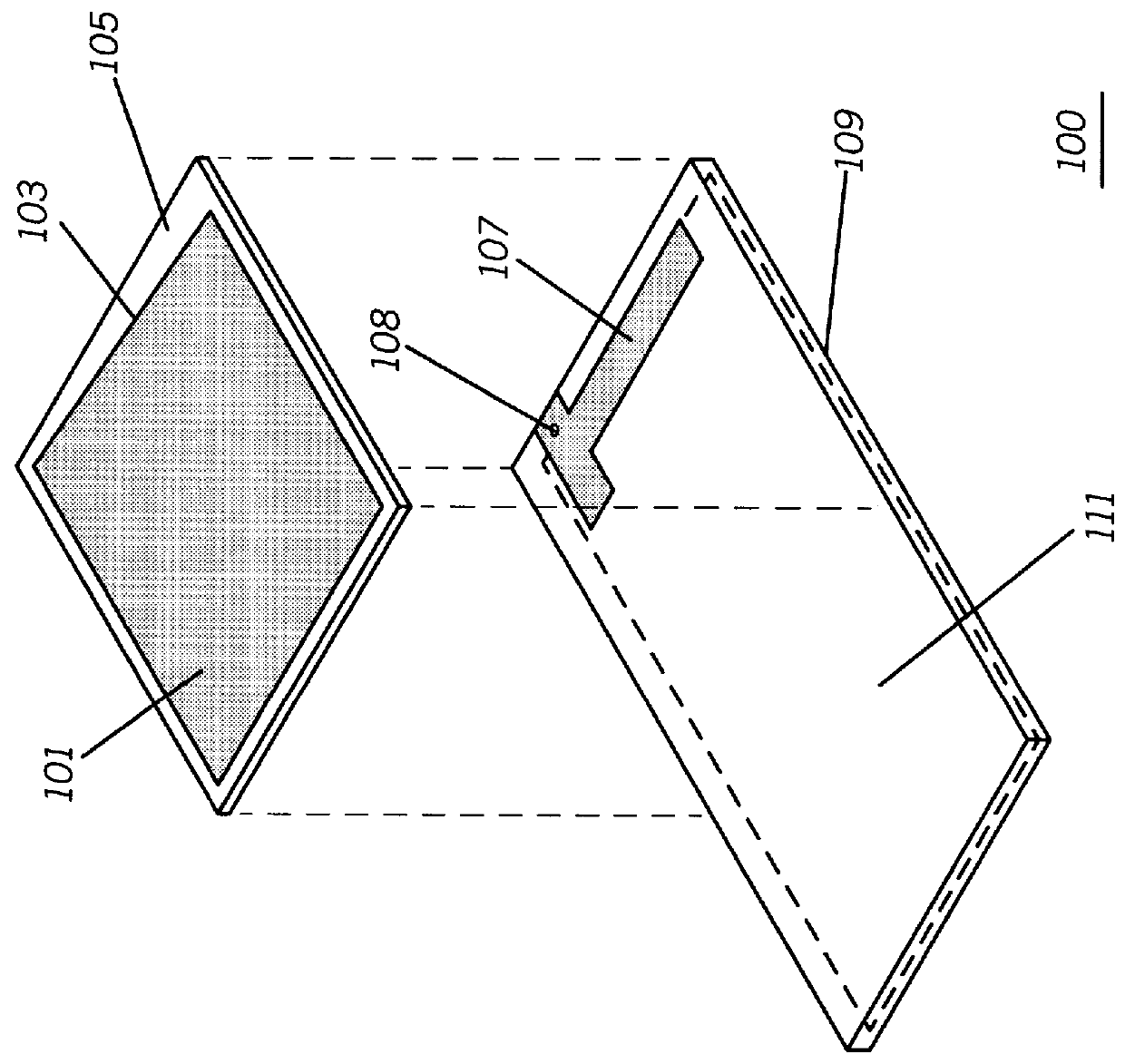
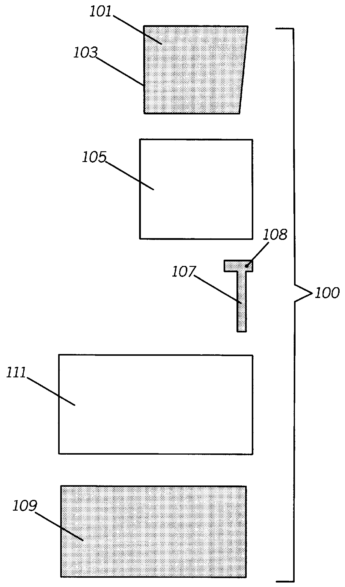
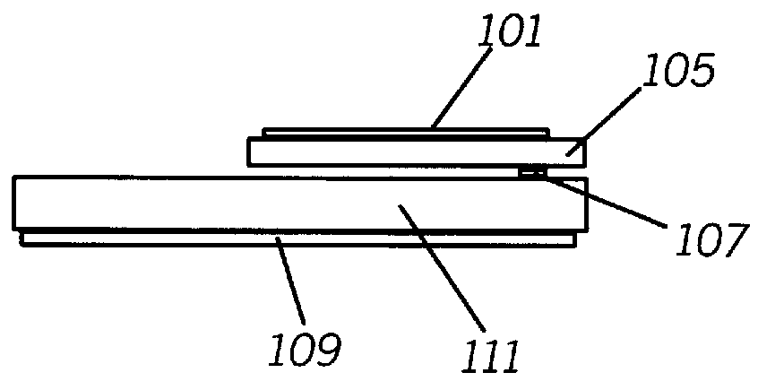
Referring now to FIG. 1, the double resonant wide band patch antenna 100 includes a planar resonator 101 formed into a trapezoidal shape. The planar resonator 101 is positioned on a substrate 105 and includes a non-parallel edge of 103. The non-parallel edge of 103 is offset at an angle of approximately ten degrees from the adjacent non-parallel side of the trapezoid. The planar resonator 101 is formed of a highly conductive material such as copper or the like and acts to radiate radio frequency (RF) energy in a uni-directional pattern. As is known in the art, the substrate 105 is typically manufactured out of a fire retarding epoxy resin / glass laminant (FR-4) but other compounds such as bismaleimide / triazine (BT) or polyimide may also be used.

Positioned below the planar resonator 101, a feedline 107 is used to couple RF energy to the planar resonator 101. The feedline 107 typically is fed from one edge of the feedline by a feed point 108. The feedline 107 has a predetermined length...


PUM


Abstract

A double resonant wideband patch antenna (100) includes a planar resonator (101) forms a substantially trapezoidal shape having a non-parallel edge (103) for providing a substantially wide bandwidth. A feed line (107) extends parallel to the non-parallel edge (103) for coupling while a ground plane (111) extends beneath the planar resonator for increasing radiation efficiency.

Description

TECHNICAL FIELDThis invention relates in general to antennas and more particularly to two-way radio patch-type antennas.BACKGROUNDPatch-type antennas are well known for use in high frequency radio frequency (RF) applications as offering acceptable losses as compared with an isotropic antennas. Moreover, a patch offers the advantage of occupying only a limited surface area. Patch type antennas typically are dimensionally flat and include a radiator that is positioned upon a section of substrate material. The patch antenna is generally unidirectional and radiates in a plane at a right angles to the surface of the radiator. Thus, depending on the orientation of the antenna, RF radiation can be directed away from a user of a portable communications device.One problem associated with the patch antenna is its narrow bandwidth. Typically this type of antenna will have a bandwidth of approximate 100 MHz at resonant frequency of 1.5 GHz with a voltage standing wave ratio (VSWR) of 2:1 or les...

Claims


Application Information

Patent Timeline
IPC IPC(8): H01Q9/04H01Q1/38H01Q5/00H01Q5/342H01Q5/378
CPCH01Q1/38H01Q5/378H01Q5/342H01Q9/0442
Inventor MCCOY, DANNY O.BALZANO, QUIRINO
Owner MOTOROLA INC
Why Eureka
Try Eureka