Process control of electrophotographic device

a technology of electrophotography and process control, which is applied in the direction of electrographic process equipment, printing, instruments, etc., can solve the problems of increasing dust production, reducing the develop ability of toner, and affecting so as to achieve the effect of improving the linearity of the tone scal

Inactive Publication Date: 2000-03-07
TEXAS INSTR INC +1
View PDF6 Cites 20 Cited by
  • Summary
  • Abstract
  • Description
  • Claims
  • Application Information

AI Technical Summary

Benefits of technology

It is therefore a first object of the invention to provide methods and devices for halftone image printi...

Problems solved by technology

Disadvantages of this technique are:
extremely low toner charge Q/M at high relative humidity RH, leading to an increase in dust production, fogging and possibly inconsistent transfer quality over the whole tone scale.
extremely high toner charge at low relative humidity, decreasing the develop ability of the toner.
Generally, on...

Method used


Image

  • Process control of electrophotographic device
  • Process control of electrophotographic device
  • Process control of electrophotographic device

Examples


Embodiment Construction

Electrophotographic engine

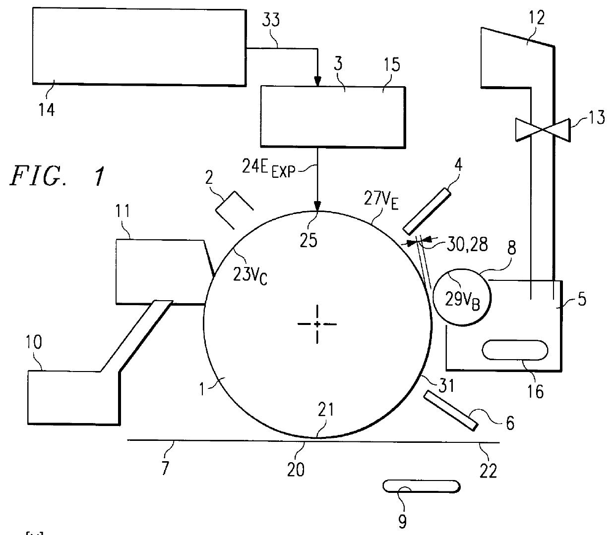
The most important components of an electrophotographic imaging apparatus suitable for the current invention are shown in FIG. 1. A photosensitive element 1, such as an OPC, is charged by a charging device 2 (such as a scorotron) and exposed by an exposure device 3 (laser scan system, LED-array, DMD, etc.). The exposure device 3 is capable of generating more than one exposure energy level E.sub.EXP per pixel. For instance a binary device can image two levels (0 and some other level different from 0), a 16-level (4 bit / pixel information) exposure device can generate 16 distinguishable levels per pixel (including 0), etc. The exposure device 3 receives image data 33 from an image processing unit 14, generally called a RIP or Raster Image Processor, which translates image data, presented in a page description language, to a bitmap. The bitmap contains the required exposure tone level I for each pixel in the image. Inside the exposure device 3 there is preferab...


PUM


Abstract

A method is described to control the maximum density and the pixel profile of microdots produced by a binary or multilevel electrophotographic device. In various embodiments, from the maximum development potential. The working point of the device is established by imposing a relation between charge level, discharge level and saturation voltage level of the photosensitive element. This allows to achieve consistent output densities, irrespective of the environmental parameters, such as relative humidity and temperature.

Description

FIELD OF THE INVENTIONThe present invention relates to devices and methods for hardcopy printing. More specifically the invention is related to a hardcopy device that has an exposure subsystem that is responsible for the generation of a latent image on a photosensitive medium. This medium may be the final image carrier after development or alternatively an intermediate member, where the latent images are developed using developers of the appropriate colours and where the developed sub-images are transferred to the final substrate as is the case in electrophotography.More specifically, the present invention relates to devices and methods for an image forming apparatus, such as an electrophotographic digital copying machine or digital printer with a two-component development system.BACKGROUND OF THE INVENTIONVarious electronic devices are available on the market that transform a digital or electronic image to appropriate density variations on an image carrier, in order to render the e...

Claims


Application Information

Patent Timeline
IPC IPC(8): B41J2/385G03G13/00G03G13/04G03G15/00
CPCB41J2/385G03G13/04G03G15/00G03G15/0266G03G15/5037
Inventor BRODDIN, DIRK K.SLABBAERT, JEAN-PIERRE J.DESCHUYTERE, FRANK A.JANSSENS, ROBERT F.HEIRBAUT, WERNER F.NELSON, WILLIAM E.EASWAR, VENKAT V.
Owner TEXAS INSTR INC
Why Eureka
Try Eureka