Dumping bay with fume collecting provisions

a technology of fume collection and dumping bay, which is applied in the direction of casting apparatus, metal-working apparatus, blast furnaces, etc., can solve the problems of undesirable use of movable hoods, emission of copious amounts of lead-containing fumes, dust and gases, and certain metallurgical processing operations

Inactive Publication Date: 2000-03-14
REPUBLIC ENGIEERED PROD INC +2
View PDF21 Cites 4 Cited by
  • Summary
  • Abstract
  • Description
  • Claims
  • Application Information

AI Technical Summary

Problems solved by technology

It is well known that certain metallurgical processing operations emit or generate hazardous, or at least potentially hazardous, fumes and dust.
As will be appreciated, this operation results in the emission of copious amounts of lead-containing fumes, dust, and gases during the dumping operation.
Although satisfactory in many respects, there are several disadvantages associated with each approach.
The use of a movable hood assembly is undesirable in that the hood must be properly placed alongside the vessel or container of interest.
This is not possible if the vessel is still relatively hot.
These operations all require additional labor.
The hardware associated with this technique is also relatively expensive.
The third approach, i.e. the use of a ducted cover without any other fume collecting provisions, is not feasible when the ves

Method used


Image

  • Dumping bay with fume collecting provisions
  • Dumping bay with fume collecting provisions
  • Dumping bay with fume collecting provisions

Examples


Embodiment Construction

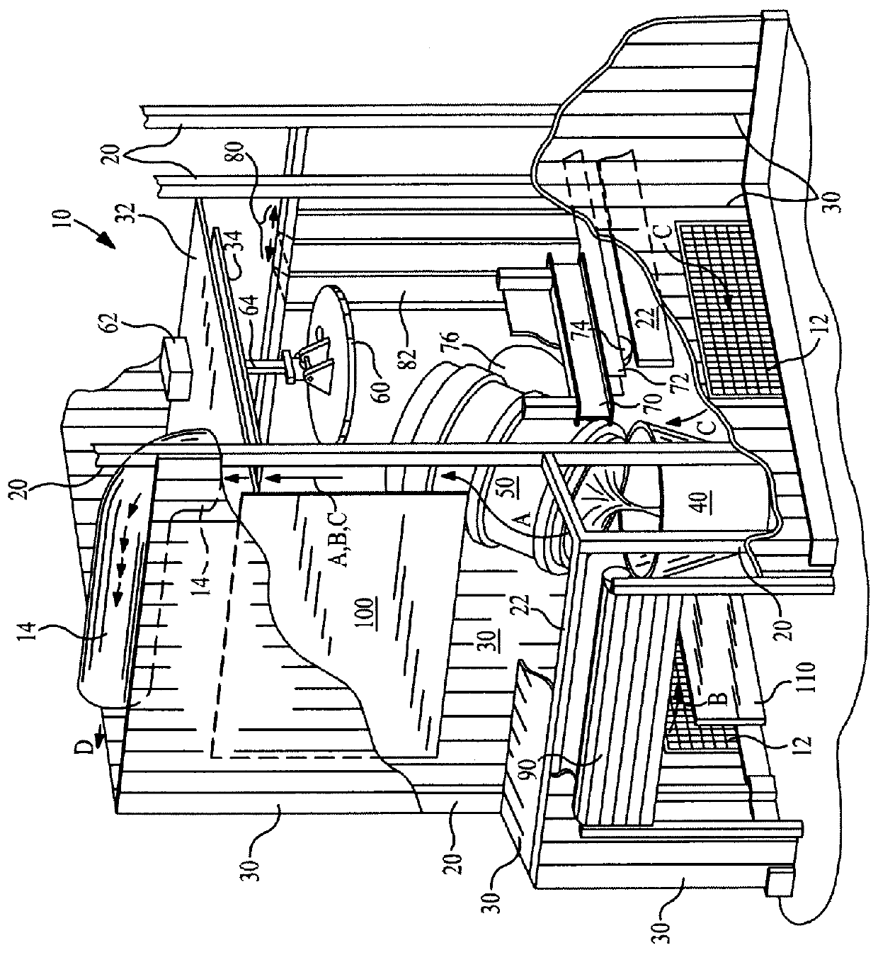
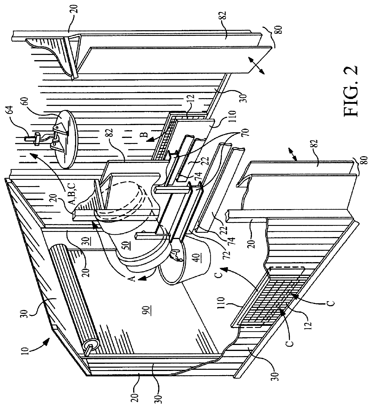
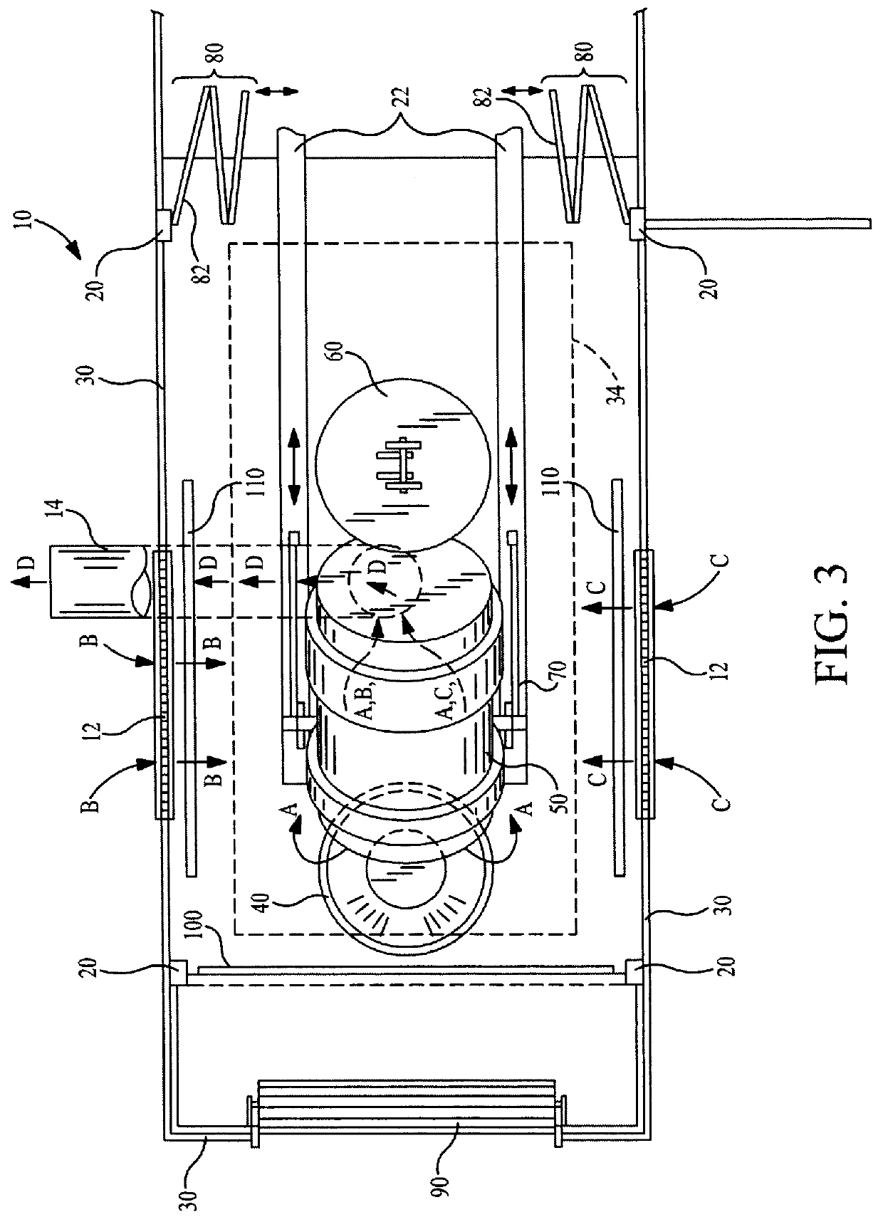
FIG. 1 illustrates a preferred embodiment dumping bay 10 in accordance with the present invention. The dumping bay 10 is particularly adapted to capture and collect hazardous agents emitted within its interior. The term "hazardous agents" as used herein includes agents, components, and particles of materials or components that are hazardous or potentially hazardous to human health, or which are considered to be pollutants or contaminants and which may be carried, entrained, or otherwise transported by a moving air flow or gas flow. The preferred embodiment dumping bay 10 comprises a frame assembly including a plurality of vertical support members 20 and horizontal support members 22, an exterior wall 30 supported by the support members 20 and 22 and generally defining the bounds of the dumping bay 10, a top wall 32, and one or more protective panels 34, heat shields 100, and protective lower panels 110 disposed within the dumping bay 10.

The dumping bay 10 houses a first metallurgica...


PUM

PropertyMeasurementUnit
Flow rateaaaaaaaaaa
Areaaaaaaaaaaa

Abstract

An improved dumping bay particularly adapted for preventing the escape of hazardous fumes into other areas of a facility is disclosed. The dumping bay is fully enclosed and utilizes a unique air flow routing technique for collecting fumes, such as from a ladle during a slag dumping operation.

Description

1. Field of the InventionThe present invention relates to a fully enclosed and self-contained dumping bay such as may be utilized in metallurgical operations, and particularly, for example, in steelmaking. The dumping bay has among other features, fume collecting provisions for capturing and collecting hazardous fumes emitted within its interior.2. Description of the Related ArtIt is well known that certain metallurgical processing operations emit or generate hazardous, or at least potentially hazardous, fumes and dust. This is particularly the case in the manufacture of leaded steel in which hazardous fumes and dust containing the known carcinogen lead, are emitted.Significant amounts of lead-containing fumes or dust are emitted when dumping slag from the manufacture of leaded steel. This operation involves transporting an empty or nearly empty ladle, however still containing slag, to an area at which the contents of the ladle are transferred to a slag pot. Typically, this transfer...

Claims


Application Information

Patent Timeline
IPC IPC(8): B22D45/00C21B3/00C21C5/28C21B3/10C21C5/40F27D17/00F27D3/14F27D23/00F27D99/00
CPCB22D45/005C21B3/10C21C5/40F27D3/145F27D17/001F27D2099/0088Y10S266/903
Inventor DIEDERICH, DAVID J.PADDOCK, JOHN C.BERNARDING, THOMAS F.WATKINS, DONALD M.
Owner REPUBLIC ENGIEERED PROD INC
Why Eureka
Try Eureka