Network system for transmitting a plurality of channels, and node device, packet transmission method, terminal equipment connection table generation method, and connection information registration method used in the system

Inactive Publication Date: 2000-03-28
CANON KK
View PDF7 Cites 28 Cited by
  • Summary
  • Abstract
  • Description
  • Claims
  • Application Information

AI Technical Summary

Benefits of technology

(5) In order to obtain the same effect as in (4), the following arrangement may be used. In the first and second steps, the packets transmitted to the target node device in each of the first and second steps and corresponding in number to all the channels received by the target node device are sequentially transmitted in an order in which the target node device receives the packet transmitted using th

Problems solved by technology

In the first and second multihop systems, since each decoder has a large hardware scale, as will be described below, each node device becomes expensive.
Furthermore, the table address generator requires a longer time for generating table addresses as the number of input coincidence signals increases

Method used


Image

  • Network system for transmitting a plurality of channels, and node device, packet transmission method, terminal equipment connection table generation method, and connection information registration method used in the system
  • Network system for transmitting a plurality of channels, and node device, packet transmission method, terminal equipment connection table generation method, and connection information registration method used in the system
  • Network system for transmitting a plurality of channels, and node device, packet transmission method, terminal equipment connection table generation method, and connection information registration method used in the system

Examples


second embodiment

(Second Embodiment)

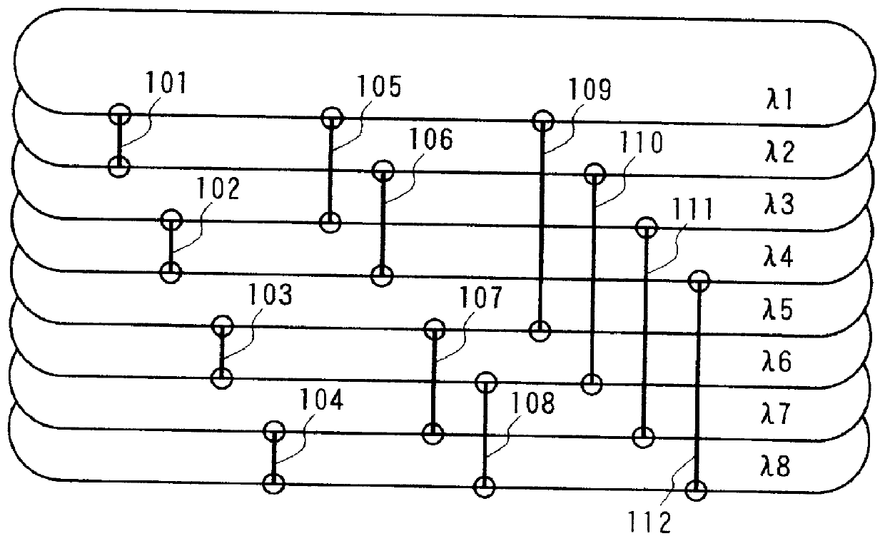
Table 2 below shows another example of the values in sections for designation of wavelengths in use of relaying node devices of the first embodiment of the present invention. As the values in sections for designation of the wavelengths in use of relaying node devices, "1" to "8" are assigned in correspondence with transmission wavelengths .lambda.1 to .lambda.8. FIG. 14 shows an embodiment of the above-mentioned packet A using Table 2 below. In this embodiment, since the wavelength to be used is designated by a serial number assigned to each wavelength in place of a value indicating a shorter or longer wavelength, each node device can easily change its transmission / reception wavelength.

TABLE 2 ______________________________________ Value in Section for Designation of Wavelength Wavelength Used by in Use of Relaying Node Relaying Node Device Device ______________________________________ 1 1 2 2 3 3 4 4 5 5 6 7 7 8 ______________________________________ Value in Sec...

third embodiment

(Third Embodiment)

FIG. 15 shows the format of a packet according to the third embodiment of the present invention, which packet is suitably used in the second multihop system shown in FIGS. 5 and 6.

In the first and second embodiments, since channels (wavelengths) that can be output from an intermediate relaying node device are predetermined, the source of a packet must indicate the number of relayings by the number of sections for designation of wavelengths in use of relaying node devices, and must designate channels to be used in units of relaying node devices.

However, in the network arrangement of this embodiment, since each relaying node device has no limitation on channels (wavelengths) to be output, and can output a packet using a desired channel, the output channels need not be designated in units of relaying node devices.

Referring to FIG. 15, a section 1501 for indication of the number of relayings indicates the number of relayings required for transmitting a packet from a no...

fourth embodiment

(Fourth Embodiment)

As in the third embodiment, when the output channels of each node device are not limited like in the above-mentioned second multihop system, the output channel need only be designated in the node device immediately before the last node device. As has been exemplified in the third embodiment, when a packet is to be transmitted from the node device I 601 to the node device IV 604 in FIG. 6, the packet can be input to only the node device IV 604 as the last relaying node device using the channel designated by the value in the section 1502 for designation of the channel. Therefore, at this time, the output channel of the packet in the node devices I 601 and II 602 is not particularly limited. Such communication method can be realized in such a manner that the packet can be stored in any memory region of the dual port memory 1709 when the value in the section for indication of the number of relayings is other than "1" in the third embodiment. Alternatively, the followi...


PUM


Abstract

A source terminal equipment connected to a node device transmits a packet by appending a section for designating the channel to be used upon relaying the packet by the node device to the packet. The relaying node device determines the channel used upon outputting the packet by looking up the value in the section for designation of the channel. The source terminal equipment transmits the packet by appending relaying number information indicating the number of relayings of the packet to the packet. Each node device looks up the relaying number information upon looking up the value in the section for designation of the channel. When each node device outputs a packet to a terminal equipment using a separation device for separating the packet toward the sub transmission path side, the node devices determines, based on the relaying number information, whether or not it separates the packet. This invention also discloses a method of generating a terminal equipment connection table and a method of registering connection information using the above-mentioned transmission method.

Description

BACKGROUND OF THE INVENTION1. Field of the InventionThe present invention relates to a network system, a node device and a communication method for the network system and, more particularly, to a node device for connecting a plurality of terminal equipments, a network system constituted by a channel multiplex transmission path using a plurality of channels (wavelengths or the like) for connecting a plurality of node devices, and a multihop transmission method, in the node device and the network system, for converting data to be transmitted into a packet, and relaying and transmitting the packet by a node device or devices located on the transmission route between the source terminal equipment and the destination terminal equipment.The present invention also relates to a terminal equipment connection table generation method for setting packet addresses, and a connection information registration method for registering connection information of the own terminal equipment to the network...

Claims


Application Information

Patent Timeline
IPC IPC(8): H04J14/02
CPCH04J14/02H04L45/00
Inventor YAMAMOTO, MITSURU
Owner CANON KK
Why Eureka
Try Eureka