
Zoom lens barrel assembly for a camera

Inactive Publication Date: 2000-04-04
FUJI PHOTO OPTICAL CO LTD
View PDF5 Cites 17 Cited by
  • Summary
  • Abstract
  • Description
  • Claims
  • Application Information

AI Technical Summary

Benefits of technology

It is another object of the invention to provide a zoom lens barrel assembly which is compact in overall size and provided at low costs.
According to the zoom lens barrel assembly of the invention, focusing and zoom ratio adjusting are selectively effected by operating the clutch mechanism, which makes it easy to achieve focusing and zoom ratio adjusting by means of a single power drive device such as an electric motor. The ring member equipped with the second guide means for focusing is mechanically coupled to the second barrel equipped with the first guide means to shift the second lens group according to the first guide means for adjusting a zoom ratio, and is permitted to rotate relatively to the second barrel to shift the second lens group according to the first and second guide means for focusing. The clutch mechanism makes the zoom lens barrel simple in structure and stable in operation for selectively achieving focusing and zoom ratio adjusting. Furthermore, the clutch mechanism incorporating en electromagnetic solenoid as an actuator of thereof ensures reliable positioning of the zoom lens in any predetermined zoom position and accurate focusing in any zoom position.

Problems solved by technology

The utilization of two power drive elements always yields an increase in camera price.
The single power drive element cooperating with separate drive mechanisms for focusing and zoom ratio adjusting always needs an increased number of parts with an adverse effects of not only increasing costs but also increasing an overall size of the camera.
The combination of a single power drive element and a common drive mechanism has a necessity for providing alternate lens guide cam slots for focusing and zoom ratio adjusting which makes a lens drive mechanism quite complex.
While the last zoom lens drive system can remove the above drawbacks, however, the locking mechanism incorporates an electromagnetic solenoid to disconnect cooperation of one of the two lens groups with its associated cam to lock the axial movement of the lens group and holds the lens group with friction only so as to remain immovable which possibly leads to unstable focusing operation.

Method used


Image

  • Zoom lens barrel assembly for a camera
  • Zoom lens barrel assembly for a camera
  • Zoom lens barrel assembly for a camera

Examples


Embodiment Construction

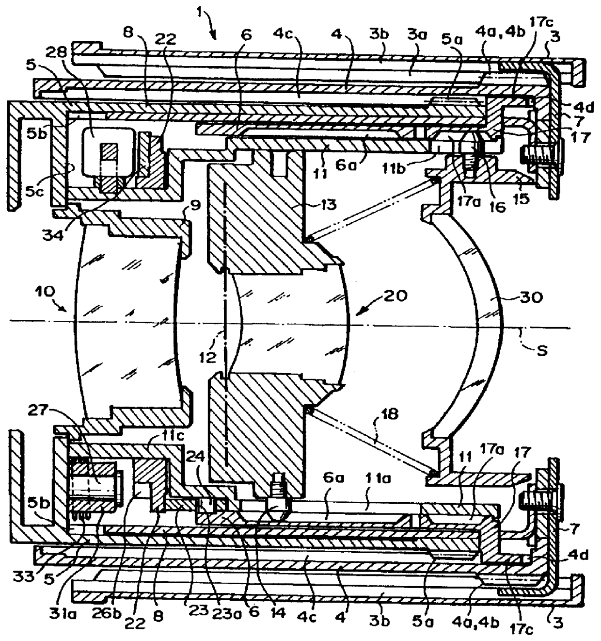
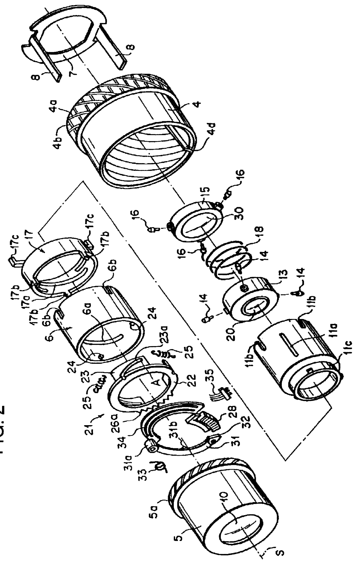
Because zoom lens barrel assemblies are well known, the present description will be directed in particular to elements and mechanisms forming part of, or cooperating directly with, assembly in accordance with the present invention. It is to be understood that elements not specifically shown or described can take various forms well known to those skilled in the art.

Referring to the drawings in detail, in particular, to FIGS. 1 and 2 schematically showing a zoom lens barrel assembly 1 in accordance with an embodiment of the invention, the zoom lens barrel assembly 1, which holds a zoom lens consisting of, for example in this example, first to third lens groups 10, 20 and 30, comprises cylindrical lens barrels coaxially arranged along an optical axis S of a zoom lens, namely an outer lens barrel 3 fixedly mounted to a camera body (not shown), a first intermediate lens barrel or first rotatable lens barrel 4 disposed to rotate in the outer lens barrel 3, a second intermediate lens barre...


PUM


Abstract

A zoom lens assembly for a zoom lens having at least two lens groups comprises at least one rotatable lens barrel equipped with a first guide cam for shifting one of the two lens group relative to the lens barrel along the optical axis, a rotatable ring member equipped with a second guide cam for shifting the lens barrel along the optical axis and an electromagnetically operated clutch mechanism for locking the rotatable ring member to permit relative rotation of the lens barrel to the ring member so as to shift the lens group according to the first and second guide cams for focusing the zoom lens and unlocking the rotatable ring member from the lens barrel to cause integral rotation of the rotatable ring member and the lens barrel so as to shift the lens group according to the first guide cam only for adjusting a zoom ratio of the zoom lens.

Description

1. Field of the InventionThis invention relates to a zoom lens barrel assembly for a camera, and, more particularly, to a power driven zoom lens barrel assembly for a camera which is operated by a single power drive element to achieve both adjusting a zoom ratio of the zoom lens and focusing the zoom lens.2. Description of Related ArtIn most zoom lenses, lens groups of the zoom lens are moved along optical axis by means of a cam mechanism differently between focusing the zoom lens on a subject and adjusting a zoom ratio of the zoom lens. To enable the zoom lens to achieve focusing and zooming by means of a power drive mechanism, there have been proposed several techniques. Specifically, one of the techniques employs separate power drive elements such as electric motors for focusing and zoom ratio adjusting, respectively. Another technique employs a single power drive element. In the case where a single power drive element is used for both focusing and zoom ratio adjusting, there hav...

Claims


Application Information

Patent Timeline
IPC IPC(8): G02B7/10
CPCG02B7/10
Inventor ONDA, KAZUHIKO
Owner FUJI PHOTO OPTICAL CO LTD
Features
  • Generate Ideas
  • Intellectual Property
  • Life Sciences
  • Materials
  • Tech Scout
  • Unparalleled Data Quality
  • Higher Quality Content
  • 60% Fewer Hallucinations
Learn More