Device fabrication involving surface planarization

a technology of surface topography and device, applied in the field of device fabrication, can solve the problems of affecting the reliability of device interconnection, and presenting significant challenges in surface topography

Inactive Publication Date: 2000-04-11
LUCENT TECH INC
View PDF6 Cites 67 Cited by
  • Summary
  • Abstract
  • Description
  • Claims
  • Application Information

AI Technical Summary

Problems solved by technology

Surface topography presents significant challenges in processes for device fabrication.
This lack of image focus uniformity degrades the resulting pattern.
Also, surface topography adversely affects device interconnect reliability because a metal layer which is deposited over such surface irregularities has turns or bends which conform to the shape of the irregularity.
These bends or turns potentially cause failures of the metal layer due to current crowding.
Although the conventional etch-back technique is adequate for some applications there is a limit to the degree of planarization provided by this technique.
Such a low degree of planarization is attributed to a lack of planarity in the planarizing material layer that is formed over the topographic substrate.
Thus, for elongated gap type features which are greater than about 100 .mu.n in width and 0.5 .mu.m in depth, the usefulness of the conventional etch-back technique, is limited.
Although this technique, in principle, yields surfaces that are planar, it requires a high degree of process control to obtain the desired results, due to the degradation of the polishing pad and of the chemical slurry during the polishing process.
This prevents the CMP technique from forming a surface having a high degree of planarity, since such concave regions are typically not completely planarized during the polishing step.
If only a portion of the flat surface of the object contacts the planarization material in the second area during the planarization step, the improvement in the planarity of the layer of planarization material is limited.
If a significant amount of planarization material flows off the substrate during planarization, the resulting planarity will be adversely affected.
Such particle adhesion has the potential to degrade the planarity of the planarization material.
Heights on the order of many times the height of the highest topographic feature are not desirable because they require longer times for performing subsequent processing steps (e.g., the etch step used to transfer the surface configuration of the planarization material into the substrate material on the topographic surface).
Heights less than the height of the highest topographic feature are also not desirable because the resulting planarity is potentially degraded.
Thus, for example, heights greater than about 10 .mu.m (micrometers) over a 2 .mu.m feature, or heights less than the height of the 2 .mu.m feature are generally undesirable.
When the object and the planarization material are separated, particles of planarizing material potentially adhere to the flat surface of the object This particle adhesion has the potential to degrade the planarity of the planarization material.
A layer of release material 20 that is not adequately uniform will negatively affect the planarity of the planarizing material.
However, there is one type of thickness nonuniformity that is acceptable.

Method used


Image

  • Device fabrication involving surface planarization
  • Device fabrication involving surface planarization
  • Device fabrication involving surface planarization

Examples


example 2

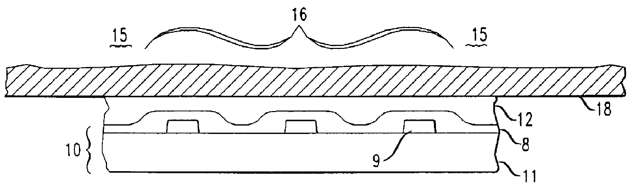
A 6 inch silicon wafer was prepared having topographic features as described in Example 1. A profilometer trace for the SiO.sub.2 features is illustrated in FIG. 11. The feature edge, denoted as 30 on the trace of FIG. 11, depicts a height of 5000 .ANG. for such SiO.sub.2 feature.

The silicon wafer was coated with DEN-431 and the area proximate to the perimeter was partially cured using the materials and conditions described in Example 1. A 9 inch diameter disk of FEP teflon having a thickness of about 0.02 inches was placed between the optical flat and the layer of DEN-431. The thickness of the teflon disk did not vary by more than about 1000 .ANG. over the 9 inch diameter. Thereafter, the layer of DEN-431 was planarized and solidified using the same conditions described in Example 1.

After the DEN-431 was solidified, the optical flat was removed from contact with the teflon film, and the teflon film was removed from contact with the DEN-431. The coated silicon wafer was analyzed to ...

example 3

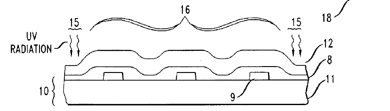
A 6" silicon wafer was prepared having topographic features as described in Example 1. A profilometer trace for the SiO.sub.2 features is illustrated in FIG. 13. The feature edge, denoted as 40 on the trace of FIG. 13, depicts a height of 5000 .ANG. for such SiO.sub.2 feature.

The silicon wafer was coated with DEN-431 using the materials and conditions described in Example 1. Thereafter, the layer of DEN-431 was placed in contact with an optical flat with a force such that the layer of DEN-431 did not significantly flow. While in contact with the flat surface of the object, a 2-3 mm width measured around the perimeter of the layer of DEN-431 was partially solidified, according to the conditions described in Example 1.

The DEN-431 was subsequently planarized and solidified according to the conditions used in Example 1. The optical flat was thereafter removed from contact with the DEN-431. The coated silicon wafer was analyzed to determine the degree of planarity achieved over the wafer...


PUM

PropertyMeasurementUnit
widthaaaaaaaaaa
widthaaaaaaaaaa
distanceaaaaaaaaaa

Abstract

A method for improving the planarity of a layer of material formed on the surface of a topographic substrate, is disclosed. The layer of planarization material formed over the topographic substrate has a first area and a second area. The planarization material in the first area is proximate to the perimeter of the topographic substrate and surrounds the planarization material in the second area. The planarization material in the first area is partially solidified, so that the planarization material in the second area is substantially confined throughout the height of the planarization material in the first area and remains within the perimeter of the topographic substrate when the surface of the layer of planarization material is planarized. The planarization material is planarized by contacting such material with a flat surface of an object with sufficient force to transfer the surface flatness from the flat surface of the object to the layer of planarization material. A release material is optionally placed between the layer of planarization material and the object with the flat surface to facilitate separation of the flat surface of the object from contact with the layer of planarization material after planarization and solidification.

Description

1. FIELD OF THE INVENTIONThe present invention relates to device fabrication, and more particularly, to device fabrication requiring the planarization of a nonplanar surface.2. DESCRIPTION OF THE RELATED ARTIn processes for device fabrication, multiple layers are formed sequentially on a substrate. Typically, at least some of these layers are patterned; i.e., the layer is formed over a portion of the substrate. Since the patterned layers do not provide a uniform thickness over the entire surface of the substrate, the surface of these patterned layers is referred to as topographic.Layers that are formed over a topographic surface tend to conform to the underlying topography. As illustrated in FIG. 1, a device 110 is formed on a substrate 100. A layer of dielectric 120 is formed over the device 110. Vias 130 are then formed in the dielectric 120 and filled with metal 135. More metal is then formed over the dielectric 120 on the substrate and is patterned to form the interconnects 140....

Claims


Application Information

Patent Timeline
Patent Type & Authority Patents(United States)
IPC IPC(8): H01L21/70H01L21/768G03F7/09
CPCB82Y10/00H01L21/76819G03F7/094
Inventor PRYBYLA, JUDITH ANN
Owner LUCENT TECH INC
Why Eureka
Try Eureka