High impedance transponder with improved backscatter modulator for electronic identification system

a high-impedance transponder and electronic identification technology, applied in the field of electronic identification systems, can solve the problems of unsatisfactory operation range, voltage recovery, and inability to achieve the operating range of known low input impedance transponders

Inactive Publication Date: 2000-04-25
ZEBRA TECH CORP
View PDF17 Cites 94 Cited by
  • Summary
  • Abstract
  • Description
  • Claims
  • Application Information

AI Technical Summary

Benefits of technology

The transponder circuitry may include a modulator connected to the input, a signal detector connected to the modulator and logic circuitry for generating an identification code; the input may be connected directly to an antenna without an impedance matching circuit between the antenna and modulator; and a real part of a feedpoint impedance of the antenna is substantially equal to a real part of the input impedance.

Problems solved by technology

The voltage recovered and thus the operating range achievable with the known low input impedance transponders, especially those with a small integrated storage capacitor and which modulate the energizing signal at about 100% modulation depth, are not satisfactory.

Method used


Image

  • High impedance transponder with improved backscatter modulator for electronic identification system
  • High impedance transponder with improved backscatter modulator for electronic identification system
  • High impedance transponder with improved backscatter modulator for electronic identification system

Examples


Embodiment Construction

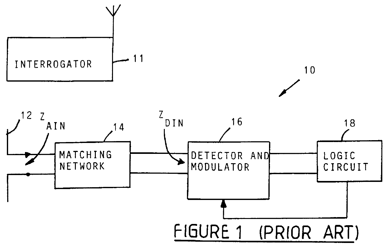
A block diagram of a prior art transponder 10 is shown in FIG. 1. The transponder 10 comprises a half wavelength dipole antenna 12 having a feedpoint impedance Z.sub.AIN of in the order of 50.OMEGA. to 100.OMEGA., typically 73.OMEGA.. A matching network 14 is provided between the antenna 12 and detector and modulator circuitry 16, to match the impedance of the antenna to the input impedance Z.sub.DIN of the detector and modulator circuitry, which typically is in the order of 125.OMEGA. to 200.OMEGA.. The detector and modulator are connected to logic circuitry 18. The detector collects power from a received interrogation signal to accumulate a voltage on a storage capacitor, to drive the logic circuitry and modulator circuit. The operational range of an interrogator 11 and transponders 10 is dependent on the voltage recovered by the detector circuit and stored on the capacitor.

The operational range of prior art systems with the aforementioned low impedance antenna (73.OMEGA.) and low...


PUM


Abstract

A transponder 20 for an electronic identification system transponder is characterized in that it presents a high input impedance (>400 OMEGA ) at an input thereof which is directly connected to an antenna 22 with a matched high input impedance. The transponder is aimed at improving the voltage recovered on capacitor C2 from an interrogation signal and thus the operational range of the system. The modulator 30 of the transponder is arranged to backscatter modulate the interrogation signal at a modulation depth of less than 80%, preferably in the order of 30%. This also results in an improvement of the operational range of the system.

Description

INTRODUCTION AND BACKGROUNDTHIS invention relates to electronic identification systems including an interrogator and a plurality of transponders. The invention more particularly relates to transponders forming part of such a system.Known electronic systems of the aforementioned kind include an interrogator including a transmitter for transmitting an interrogation signal to the transponders and a receiver for receiving a response signal from the transponders. A microprocessor in the interrogator identifies a particular transponder from a data stream in the response signal. Each transponder comprises an antenna and a detector circuit for receiving and collecting power from the interrogation signal, to present a high enough voltage on a storage capacitor, to power a modulator and logic circuitry of the transponder, which logic circuitry in turn generates the aforementioned data stream. The data stream is used to modulate the energizing signal at about 100% modulation depth and to refle...

Claims


Application Information

Patent Timeline
Patent Type & Authority Patents(United States)
IPC IPC(8): G06K19/07G01S13/76G01S13/75G01S13/79H04B1/59
CPCG06K19/0723
Inventor PROCTOR, DAVID EDWINTURNER, CHRISTOPHER GORDON GERVASE
Owner ZEBRA TECH CORP
Why Eureka
Try Eureka