Light level monitoring and ATM control system for automated teller machine which directly measures light source luminance to indirectly determine area illuminance

a control system and automated teller technology, applied in the direction of atm details, instruments, energy-saving lighting, etc., can solve the problem of increasing crimes that take place near the atm

Inactive Publication Date: 2000-05-02
PIEROTH ROBERT F
View PDF1 Cites 36 Cited by
  • Summary
  • Abstract
  • Description
  • Claims
  • Application Information

AI Technical Summary

Benefits of technology

The invention may be regarded as light level monitoring and control system for use with an automated teller machine (ATM) having a user area that is illuminated by a light fixture, the control system comprising a light sensor for measuring light energy emanating from the light fixture and outputting a signal; an illuminated display operatively connected to the controller for warning a distant user that the ATM is disabled; and a controller including: means for inputting a measured value corresponding to a measured incident light reading in the user area when the area was illuminated by the light fixture; means for inputting a

Problems solved by technology

The growing popularity of ATM use, however, has resulted in an increase in crimes that take place near the ATM.
First, because the light sensor assembly 23S must be remotely positioned relative to the ATM 12 in order to "see" the illuminated customer area, the assembly 23S must often be mounted in a position that is not conveniently serviced with wires that supply power or return light measurement signals. Accordingly, it is often necessary to use battery powered light sensor assemblies that use wireless links such as radio frequency (RF) communications, a situation that is obviously undesirable in the context of consumer safety since the batteries will discharge over time and must, therefore, be frequently serviced. The '052 patent, in fact, focuses on an RF system wherein the light sensor assembly 23S only transmits when it determines that the light is below a certain level. It seems, therefo

Method used


Image

  • Light level monitoring and ATM control system for automated teller machine which directly measures light source luminance to indirectly determine area illuminance
  • Light level monitoring and ATM control system for automated teller machine which directly measures light source luminance to indirectly determine area illuminance
  • Light level monitoring and ATM control system for automated teller machine which directly measures light source luminance to indirectly determine area illuminance

Examples


Embodiment Construction

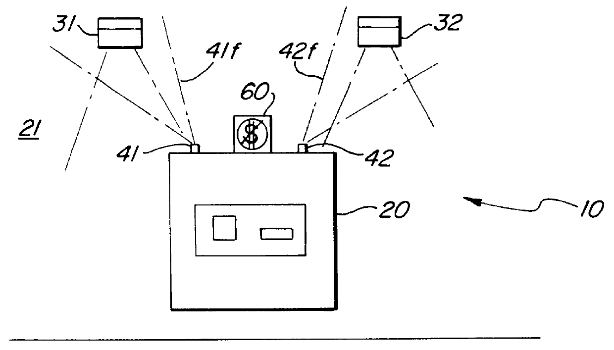
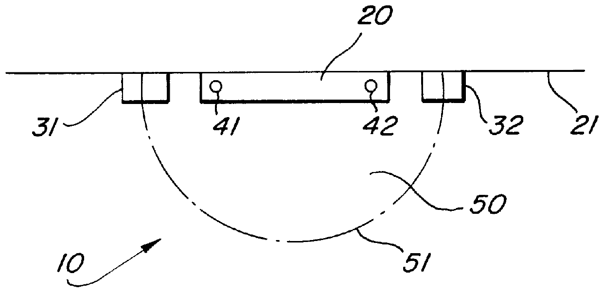
FIG. 1 shows a typical ATM installation 10 wherein an ATM 20 is mounted in a wall 21 and illuminated by a pair of light fixture 31, 32 which are located on the wall 21, above the ATM 20 and to either side thereof. The light fixtures 31, 32, as suggested by FIG. 2, provide a desired level of illumination within a user area 50. The user area 50 is open to various definition of course, but in the State of California, where banks are required to provide at least ten (10) foot-candles of illumination as measured at thirty-six (36) inches above grade and anywhere along a five (5) foot radius, the user area 50 may be regarded as bounded by the arc 51 which circumscribes the five foot radius related to the mandatory minimum light levels.

FIGS. 1 and 2 also show first and second light sensors 41, 42 and an illuminated alert sign 60, described more fully below, which are a part of a preferred embodiment of the present invention when used with the ATM installation 10 having first and second lig...


PUM


Abstract

The invention is a light level monitoring and ATM control system which is designed for operation at a typical automated teller machine (ATM). The system is used to ensure that a user area associated with the ATM is maintained at a minimum light level. If the user area drops below a predetermined minimum, the preferred system disables the ATM and illuminates a warning sign to deter bank customers from approaching the area. The system does not directly measure the light level in the user area, but rather uniquely, indirectly determines the light level in the user area by measuring the output of a light fixture that illuminates the user area at a point remote to the user area and by calibrating the remote measurement relative to a measured value and a minimum value in the user area. The system, by indirectly determining the light level in the user area, does not suffer from apparent changes in light level in the user area due to the presence or absence of a customer or the color of a customer's clothing. The light sensors associated with the light fixtures may beneficially be hardwired and remotely powered, not battery powered, because of their proximity to the wiring plant associated with the ATM and the light fixtures.

Description

1. Field of the InventionThe present invention relates generally to lighting control systems and, more particularly, to a lighting monitoring system for use with an automated teller machine (ATM) which directly measures source luminance to indirectly determine in the area surrounding the ATM and which effectively alerts customers in the event of a dimly lit and potentially dangerous condition.2. Description of the Related ArtThe typical automated teller machine (ATM) installation includes customer interactive elements such as a keypad and currency door, as well as remote communication elements such as telemetry equipment, which communicates with a central station to notify the station when the machine is out of cash or when the machine encounters mechanical failures. The typical ATM installation also includes shut down mechanisms for closing the cash door and taking the machine out of service.The growing popularity of ATM use, however, has resulted in an increase in crimes that take...

Claims


Application Information

Patent Timeline
IPC IPC(8): H05B39/00H05B37/03H05B37/00H05B39/04G07F19/00
CPCG07F19/20H05B39/042H05B37/034G07F19/205H05B47/22Y02B20/00
Inventor PIEROTH, ROBERT F.PAZEMENAS, VYTAS V.
Owner PIEROTH ROBERT F
Why Eureka
Try Eureka