

Moisture resistant underground cable
a technology of underground cable and moisture resistance, which is applied in the direction of power cables, cables, insulated conductors, etc., can solve the problems of increasing the potential for cable failure, increasing the cost of cable manufacturing, and many cable failures, and achieve good mechanical properties
- Summary
- Abstract
- Description
- Claims
- Application Information
AI Technical Summary
Benefits of technology
Problems solved by technology
Method used
Image

Examples
Embodiment Construction
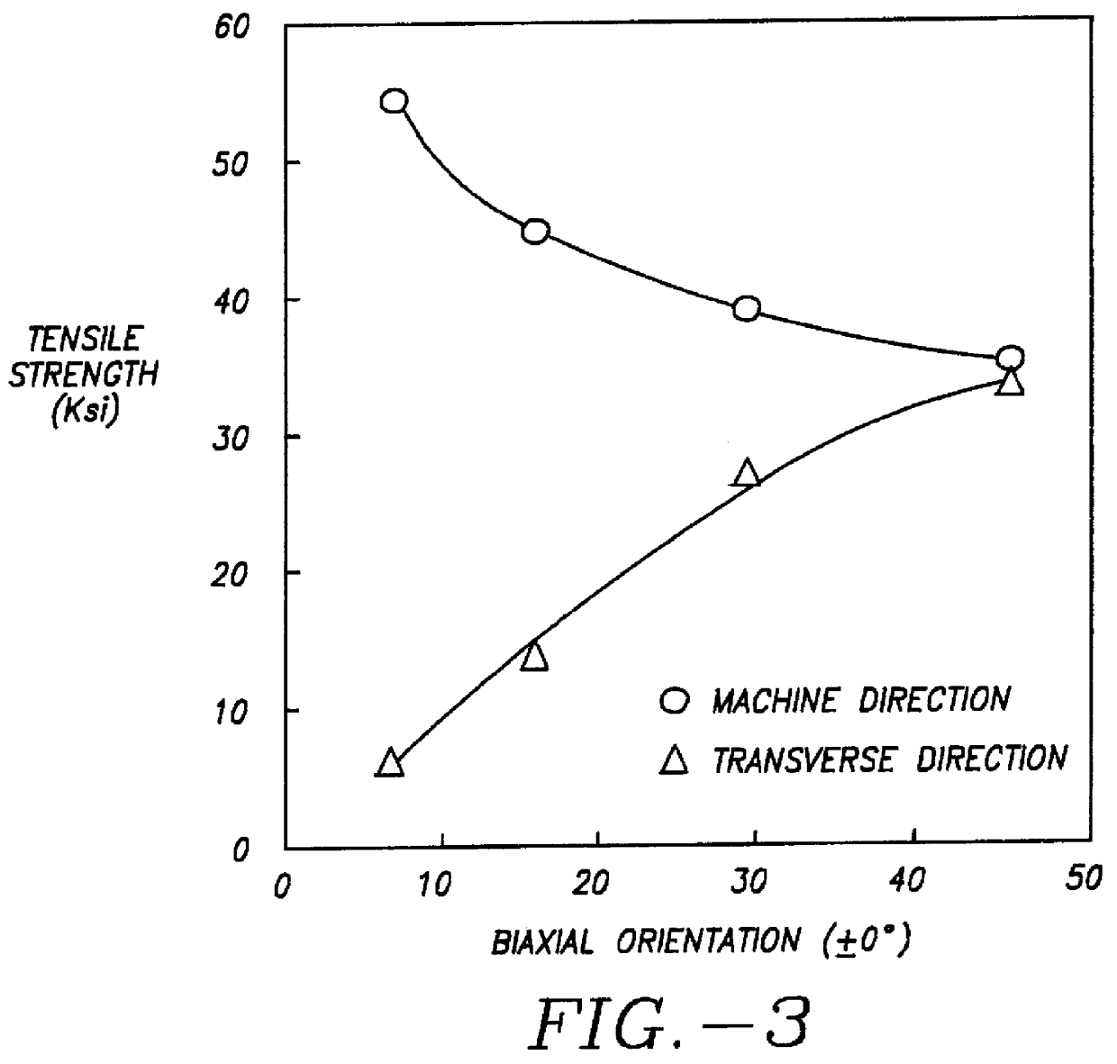
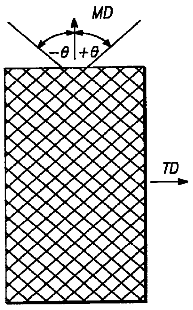
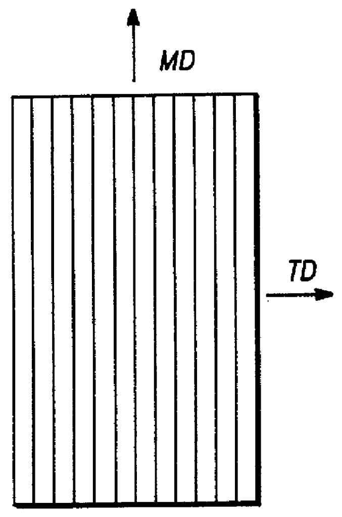
FIG. 1 schematically shows a thin LCP film formed by standard LCP extrusion processes. The film has uniaxial orientation of the molecules. This provides very high machine direction tensile strength / modulus but very low transverse direction tensile strength / modulus. In contrast, a film such as that illustrate in FIG. 2 has a biaxial molecule orientation which gives substantially equal machine direction and transverse direction strength / modulus.
Liquid crystal polymers are rigid, rod-like macromolecules, typically containing a substantial number of polyvalent aromatic groups such as phenylene. Liquid crystal polymers may be placed into a force field such as shear, in molten state or in solution, to be aligned and oriented, and they tend to retain their orientation on cooling or evaporating. This is because of the stearic hinderance of molecular rotation provided by the large number of polyvalent aromatic or other groups. Thus they exhibit a high "relaxation time", which means that they...
PUM
| Property | Measurement | Unit |
|---|---|---|
| Angle | aaaaa | aaaaa |
| Angle | aaaaa | aaaaa |
| Electrical resistance | aaaaa | aaaaa |
Abstract
Description
Claims
Application Information