Liquid crystal display with ellipsoidal polarizing plate having an optically anisotropic layer transparent substrate and a polarizing membrane

a technology of polarizing plate and liquid crystal, which is applied in the direction of thin material processing, instruments, chemistry apparatus and processes, etc., can solve the problem of color of the display image with leaked light of a specific wavelength

Inactive Publication Date: 2000-05-16
FUJIFILM CORP
View PDF15 Cites 100 Cited by
  • Summary
  • Abstract
  • Description
  • Claims
  • Application Information

AI Technical Summary

Benefits of technology

An object of the present invention is to further improve a liquid crystal display of a bend alignment mode or a homogeneous alignment mode without causing color contamination on a displayed image.
The present inventor has succeeded in improving a viewing angle of a liquid crystal display of a bend alignment mode or a homogeneous alignment mode without causing color contamination on a displayed image. The liquid crystal display is improved by changing the arrangement of the an optically anisotropic layer, a transparent substrate and a polarizing membrane.
For the reasons mentioned above, the liquid crystal display of a bend alignment mode or a homogeneous alignment mode is further improved in the viewing angle without causing color contamination on a displayed image.
The discotic compounds (31a to 31e) contained in the optically anisotropic layer (31) are planer molecules. Each of the molecules has only one plane, namely discotic plane. The discotic planes are inclined to planes parallel to the surface of the transparent substrate (33). The angle between the discotic planes and the paralleled planes are inclined. As the distance between the molecule and the orientation layer (32) increases along a normal line of the transparent substrate (33), the inclined angles increase. The average inclined angle is preferably in the range of 15 to 50.degree.. An ellipsoidal polarizing plate has a function of improving the viewing angle. The function can be further improved where the inclined angles are changed as is shown in FIG. 3. The ellipsoidal polarizing plate shown in FIG. 3 has another function of preventing an image from reversion, gray-scale inversion and color contamination of a displayed image.
The liquid crystal display of the present invention is characterized in that the wavelength dependency of the optically compensatory effect is low. The low wavelength dependency of the optically compensatory effect means that the difference between the sum of the Re retardation values of the optically anisotropic layer and the transparent substrate (total value of the layer and the substrates where two ellipsoidal polarizing plates are used) and the Re retardation value of the liquid crystal display is less than 10 nm even if the values are measured at any wavelength in the range of 400 to 700. The values can easily be obtained by arranging the optically anisotropic layer, the transparent substrate and the polarizing membrane of the ellipsoidal polarizing plate according to the present invention.
The attachment of the lamination film, the second substrate and the polarizing membrane is preferably conducted immediately after forming the optically anisotropic layer to reduce the repeating number of the processes of rolling the film up and down.

Problems solved by technology

As a result, the present inventor has found a problem that a displayed image is colored with leaked light of a specific wavelength.

Method used


Image

  • Liquid crystal display with ellipsoidal polarizing plate having an optically anisotropic layer transparent substrate and a polarizing membrane
  • Liquid crystal display with ellipsoidal polarizing plate having an optically anisotropic layer transparent substrate and a polarizing membrane
  • Liquid crystal display with ellipsoidal polarizing plate having an optically anisotropic layer transparent substrate and a polarizing membrane

Examples


example 2

(Formation of second transparent substrate)

In dichloromethane, 2,2'-bis(4-hydroxyphenyl)propane polycarbonate resin (viscosity average molecular weight: 28,000) was dissolved to obtain a 18 wt. % solution. The obtained solution was defoamed under vacuum to obtain a dope. The dope was cast on a band, dried at 50.degree. C. for 10 minutes, peeled from the band, and further dried at 100.degree. C. for 10 minutes. The obtained film was stretched by 5.5% along a longitudinal direction at 170.degree. C., and was stretched by 2.5% along a horizontal direction to obtain a biaxially stretched roll film (second transparent substrate) having the thickness of 80 .mu.m. The longitudinal stretching was controlled by the difference between the rotating speeds of two chucking rolls. The horizontal stretching was controlled by the width of a tenter.

The Re retardation value of the second transparent substrate (measured at the wavelength of 546 nm) was 30 nm, and the Rth retardation value was 200 nm.

(...

##sion example 1

Comparsion Example 1

(Formation of orientation layer)

The coating solution used in Example 1 was coated on the gelatin undercoating layer of the first transparent substrate prepared in Example 1 by using a wire bar coater of #16. The coating amount was 28 ml per m.sup.2. The coated layer was air dried at 60.degree. C. for 60 seconds, and further air dried at 90.degree. C. for 150 seconds to form an orientation layer. The formed layer was subjected to a rubbing treatment. The rubbing direction was parallel to the slow axis of the first transparent substrate (measured at the wavelength of 632.8 nm).

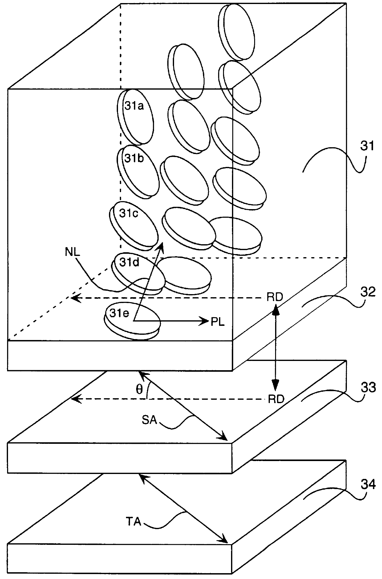
(Formation of ellipsoidal polarizing plate)

An ellipsoidal polarizing plate was prepared in the same manner as in Example 1, except that the above-prepared orientation layer was used.

The Re retardation value of the lamination comprising the optically anisotropic layer and the first and second transparent substrates was measured at the wavelength of 436 nm, 546 nm and 611.5 nm.

(Optical characte...

example 3

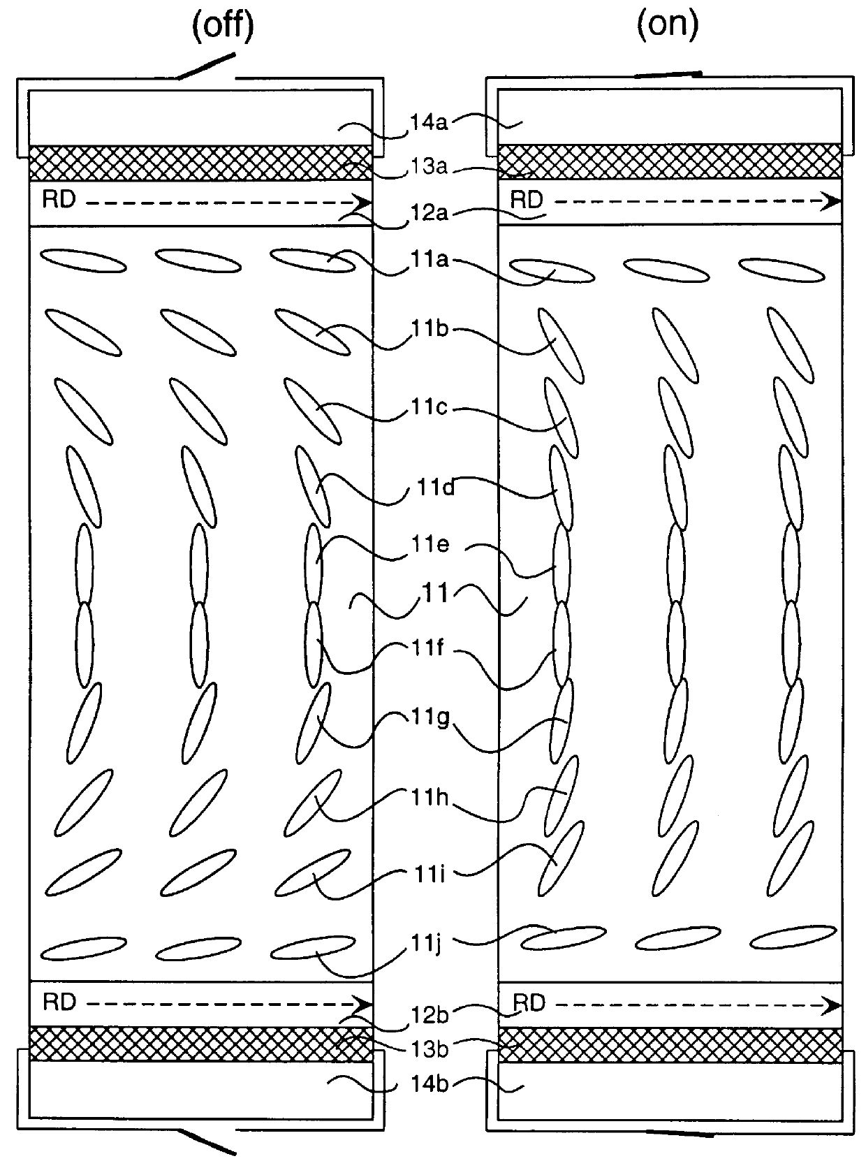
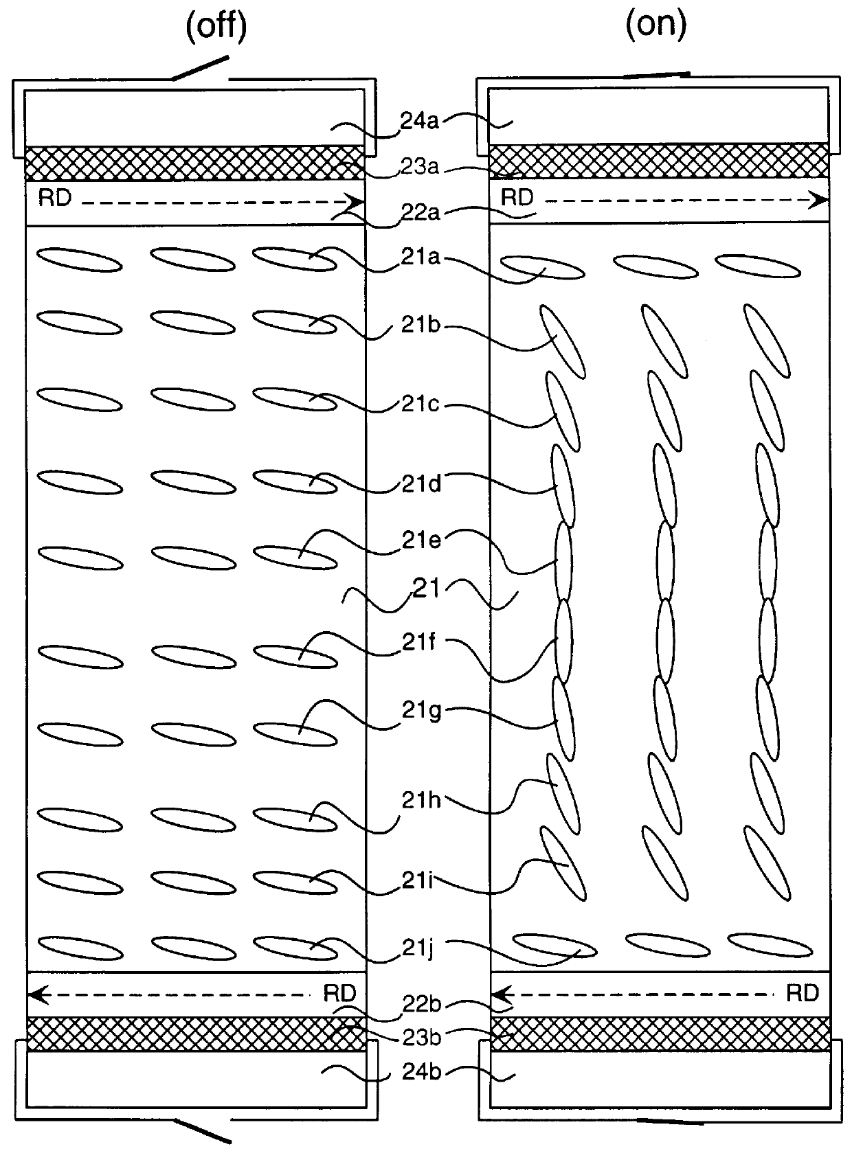
(Formation of liquid crystal cell of bend alignment mode)

On a glass plate having an ITO electrode, a polyimide film (orientation layer) was attached, and subjected to a rubbing treatment. The two glass plates were placed by facing the orientation layer with each other. The rubbing direction on one glass plate was parallel to the rubbing direction on the other plate. The cell gap was 6 .mu.m. A liquid crystal molecule having .DELTA.n of 0.1396 (ZLI1132, Merck & Co., Inc.) was injected into the cell gap to prepare a liquid crystal cell of a bend alignment mode.

The Re retardation value of the liquid crystal cell was measured at the wavelength of 436 nm, 546 nm and 611.5 nm while applying voltage (5 or 5.5 V) of a square wave (55 Hz) to the cell.

(Preparation of liquid crystal display)

Two ellipsoidal polarizing plates prepared in Example 1 were arranged on both sides of the liquid crystal cell of a bend alignment mode. The optically anisotropic layer of the ellipsoidal polarizing plate w...


PUM

PropertyMeasurementUnit
angleaaaaaaaaaa
inclined angleaaaaaaaaaa
angleaaaaaaaaaa

Abstract

A liquid crystal display comprises a liquid crystal cell of a bend alignment mode or a homogeneous alignment mode and two polarizing elements. Each of the elements is arranged on each side of the liquid crystal cell. At least one of the polarizing elements is an ellipsoidal polarizing plate. The ellipsoidal polarizing plate comprises a lamination of an optically anisotropic layer, a transparent substrate and a polarizing membrane. The optically anisotropic layer contains discotic compounds. The transparent substrate is optically anisotropic. The polarizing membrane is arranged as an outermost layer of the liquid crystal display. The optically anisotropic layer and the transparent substrate are so arranged that an angle between a normal discotic direction and a slow axis in plane of the transparent substrate is essentially 45 DEG . The normal discotic direction is an average of directions obtained by projecting normal lines of discotic planes of the discotic compounds on plane of the substrate. The transparent substrate and the polarizing membrane are so arranged that a slow axis in plane of the transparent substrate is essentially parallel to or essentially perpendicular to a transmission axis in plane of the polarizing membrane.

Description

The present invention relates to a liquid crystal display of a bend alignment mode or a homogeneous alignment mode. The invention also relates to an ellipsoidal polarizing plate used in the liquid crystal display.A liquid crystal display (LCD) has advantages of thin shape, light weight and low consumption of electric power, compared with a cathode ray tube (CRT). The liquid crystal display comprises a liquid crystal cell and two polarizing elements arranged on both sides of the liquid crystal cell. The liquid crystal cell comprises a pair of substrates, rod-like liquid crystal compounds and an electrode layer. The rod-like liquid crystal compounds are provided between the substrates. The electrode layer has a function of applying a voltage to the rod-like liquid crystal compound. Each of the substrates has an orientation layer, which has a function of aligning the rod-like liquid crystal compound.An optically compensatory sheet (a phase retarder) is usually provided between the liqu...

Claims


Application Information

Patent Timeline
Patent Type & Authority Patents(United States)
IPC IPC(8): G02F1/13G02F1/139G02F1/13363
CPCG02F1/133632G02F1/13363Y10T428/1041G02F2413/105G02F1/1393C09K2323/031
Inventor AMINAKA, EIICHIRO
Owner FUJIFILM CORP
Why Eureka
Try Eureka