Method of configuring a ceramic core for casting a turbine blade

a technology of ceramic core and turbine blade, which is applied in the direction of manufacturing tools, foundry patterns, moulding apparatus, etc., can solve the problems of insufficient thickness, insufficient brittleness of ceramic cores, and inability to mold turbine blades

Inactive Publication Date: 2000-05-30
UNITED TECH CORP
View PDF7 Cites 52 Cited by
  • Summary
  • Abstract
  • Description
  • Claims
  • Application Information

AI Technical Summary

Problems solved by technology

As one skilled in the gas turbine engine's turbine blade technology appreciates, the formation of the internal cooling passages in a turbine blade present formidable problems.
These ceramic cores are extremely brittle and the thickness is finite and obviously, have the propensity of breaking.
Because of the material and the finite sizes of these passages the producibility of the blades are adversely impacted.
This coupled with the fact that the sizes and locations of the passages internally of the blade are critical, the cooling requirements of the blades in order to maintain its structural integrity in the engine's hostile environment are severe compounds the complexity of the designer's task.
In addition the designer must be cognizant of the fact that the air utilized for cooling is taken from the engine after a certain amount of processing of this air has occurred which obviously impacts the performance of the engine.
Not only is the amount of work that has been done on that cooling air represents a penalty to the engine's performance, it is obviously necessary to utilize only that much air that will handle the cooling load.
Any extra air used for this purpose accounts for an additional deficit in the performance of the engine.
As is well known in this industry, core breakage has been a problem confronting the blade designer for some time.
a) these hybrid cores can not be thickened on both sides without displacing the main body;
b) On a 3-piece assembled core configuration, the core joints would require a matched plug and socket type of contour, increasing the potential for mismatched surfaces;
4) Flash at the core joints would occur perpendicular to the coolant flow causing blockage of the cooling air;
5) Direct access for flash removal is difficult, if not impossible; Complete flash removal causes risk of damaging the surfaces of the blade neck; and
6) There are no provisions for selectively metering coolant flow into a particular hybrid cavity.

Method used


Image

  • Method of configuring a ceramic core for casting a turbine blade
  • Method of configuring a ceramic core for casting a turbine blade
  • Method of configuring a ceramic core for casting a turbine blade

Examples


Embodiment Construction

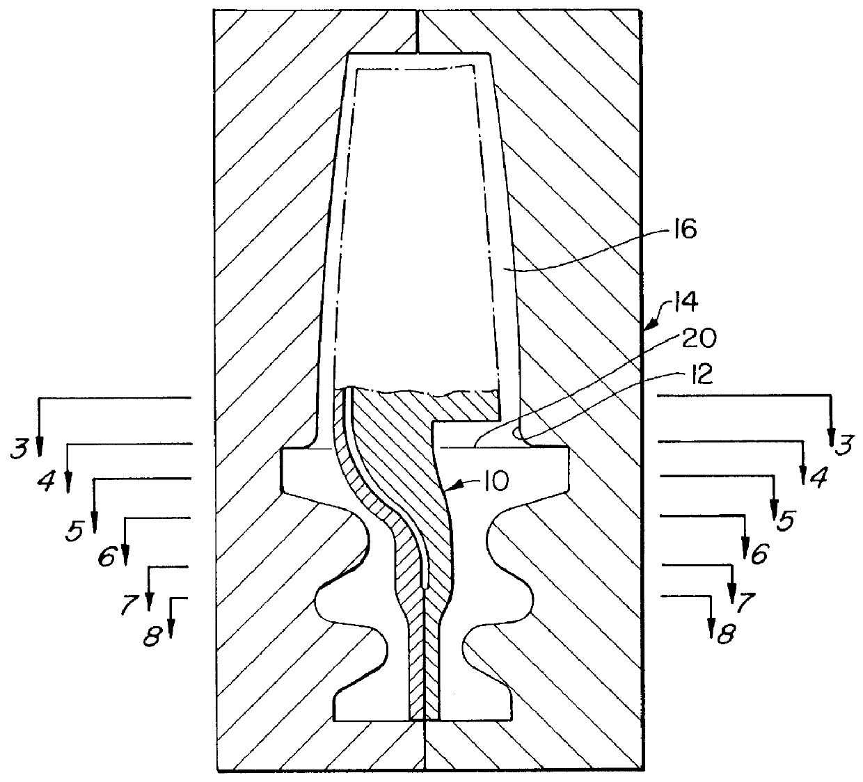
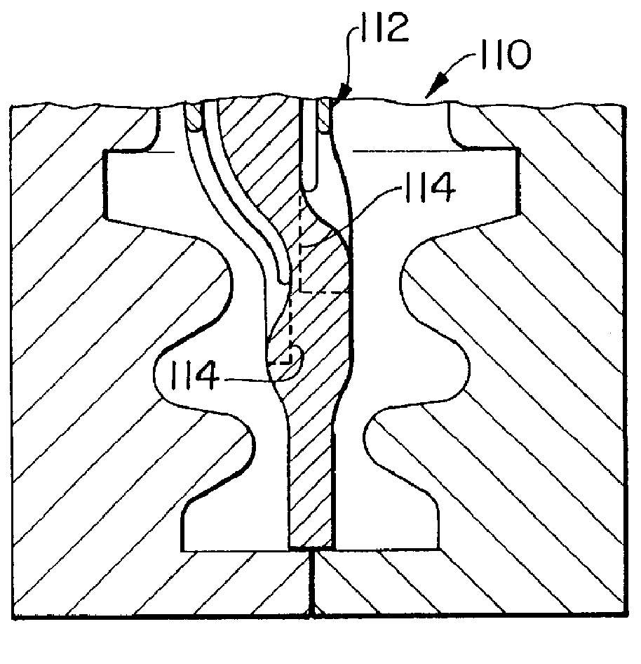
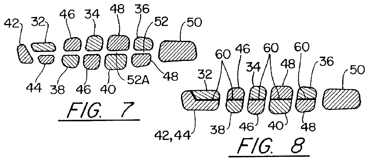
Reference is now made to FIGS. 2-10 illustrating the details of this invention. As mentioned earlier the invention is concerned with a 4-walled, cooled, single-piece cast turbine blade and teaches the unique configuration of the core which significantly enhances the producibility of both the end part and the ceramic core assembly required to make it. The configuration utilizes either a three or four piece assembled core made from a suitable ceramic material in which each piece is made using production-oriented methods and materials.

Essentially, the pieces or individual segments of the core are uniquely configured to make up the inner walls of the 4-walled casting. The segments taper and merge, alternating from either side of the airfoil while fairing radially inward, until they line up to form a single wall, parallel to and centered in the blade attachment. As will be appreciated by those skilled in this art, this configuration effectively results in a 4-walled airfoil blending into...


PUM

PropertyMeasurementUnit
pressureaaaaaaaaaa
thicknessaaaaaaaaaa
sizesaaaaaaaaaa

Abstract

The internally air cooled turbine cast blade is molded with a ceramic core for defining the interior cavity with coolant passages where the ceramic core is configured to fair radially inwardly at the attachment portion of the blade until they form a single wall, parallel to and centered in the blade attachment. The blade is cast in the mold by pouring molten metal into the mold, curing and the core is leached once the metal is cured and the mold removed. Another embodiment includes a metering plate attached to the root of the blade for metering coolant to provide a coolant to gas flow ratio at the film cooling holes.

Description

This invention was made under a Government contract and the United States Government has an interest herein.TECHNICAL FIELDThis invention relates to air cooled turbine blades for gas turbine engines and particularly to the casting configuration for molding the turbine blade and the method thereof.BACKGROUND ARTAs one skilled in the gas turbine engine's turbine blade technology appreciates, the formation of the internal cooling passages in a turbine blade present formidable problems. Typically, these passages are formed in the molding process for casting the blade utilizing ceramic cores. These ceramic cores are extremely brittle and the thickness is finite and obviously, have the propensity of breaking. Because of the material and the finite sizes of these passages the producibility of the blades are adversely impacted. Not only is the blade designer confronted with these molding problems, he must also take into consideration the effectiveness of cooling of the blades by virtue of t...

Claims


Application Information

Patent Timeline
Patent Type & Authority Patents(United States)
IPC IPC(8): B22C9/10B29C33/30B29C33/76F01D5/18B29C35/16B29C33/42B29C35/00
CPCB22C9/10B22C9/103B29C33/301F01D5/187B29C33/76B29C33/42Y10T29/49341B29C35/16B29L2031/08
Inventor DIETRICH, DOUGLAS JAMES
Owner UNITED TECH CORP
Why Eureka
Try Eureka