Cryogenic cooler with mechanically-flexible thermal interface

Inactive Publication Date: 2000-06-06
RAYTHEON CO
View PDF5 Cites 57 Cited by
  • Summary
  • Abstract
  • Description
  • Claims
  • Application Information

AI Technical Summary

Problems solved by technology

In certain applications, such as airborne missiles, this requirement tends to impose significant logistical constraints.
This limits the `on-station` life of the weapons platform in proportion to the amount of pressurized gas onboard.
Frequent recharging of Joule-Thomson cryostats increases the possibility of contamination due to small impurities which may block the fine orifice of the device.
These constraints impose significant field maintenance requirements which limit the viability of Joule-Thomson cryostats for such demanding applications.
However, this gap presents another problem: viz., how to tra

Method used


Image

  • Cryogenic cooler with mechanically-flexible thermal interface
  • Cryogenic cooler with mechanically-flexible thermal interface
  • Cryogenic cooler with mechanically-flexible thermal interface

Examples


Embodiment Construction

Illustrative embodiments and exemplary applications will now be described with reference to the accompanying drawings to disclose the advantageous teachings of the present invention.

While the present invention is described herein with reference to illustrative embodiments for particular applications, it should be understood that the invention is not limited thereto. Those having ordinary skill in the art and access to the teachings provided herein will recognize additional modifications, applications, and embodiments within the scope thereof and additional fields in which the present invention would be of significant utility.

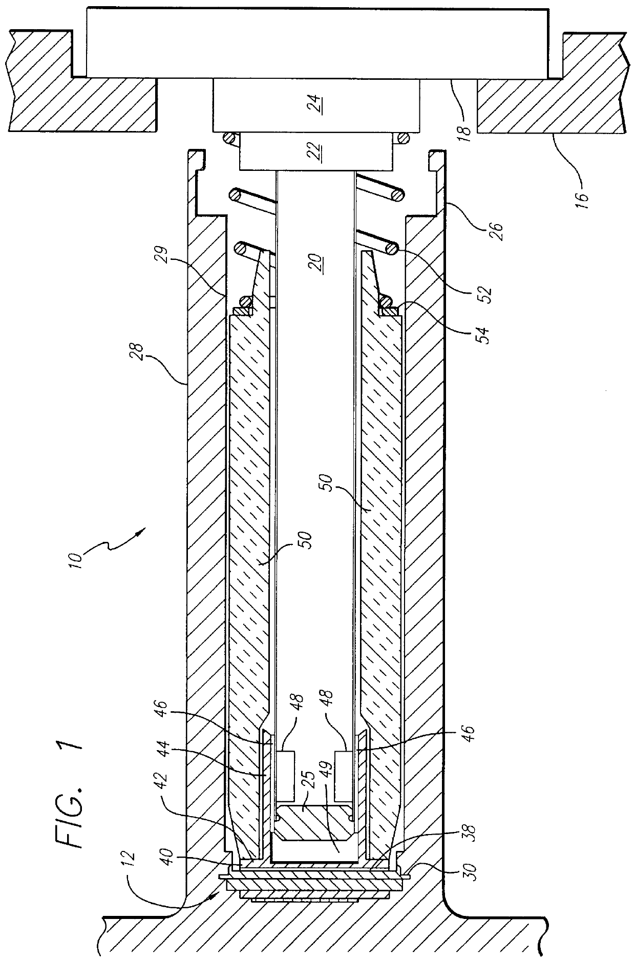
FIG. 1 is a sectional side view of an illustrative implementation of the Stirling cycle cryogenic cooler and dewar assembly of the present invention. The Stirling cooler and dewar assembly 10 is shown with a thermal load 12 attached thereto. In an illustrative missile application, the Stirling cryocooler expander 10 is mounted within a support structure such as ...


PUM


Abstract

A cryogenic cooler and a dewar assembly including a cooled surface; a cooling surface for removing thermal energy from said cooled surface; and an adapter disposed between said cooling surface and the cooled surface for conducting thermal energy therebetween. A first fluid is disposed between the cooled surface and the adapter for conducting thermal energy from the cooled surface to the adapter. A second fluid is disposed between the cooling surface and the adapter for conducting thermal energy from the adapter to the cooling surface whereby the cooling surface remains free to move axially relative to the adapter at a temperature of the cooling surface at which the first fluid is susceptible to freezing. This allows for movement of the cold finger relative to the dewar and adapter, due to differential thermal coefficients of expansion or support structure motion, without adversely affecting the communication of thermal energy from the load. In the illustrative embodiment, the cooler is a Stirling cycle cooler, the first fluid is thermal grease and the second fluid is nitrogen. The cooling surface is a cylindrical cold finger of the Stirling cycle cooler and the cooled surface is an inner wall of a dewar assembly. The dewar is in thermal contact with a load. The adapter is disposed between the inner wall of the dewar and the cold finger. The adapter has an end cap and a cylindrical housing extending therefrom. The housing extends at least partially along a longitudinal axis of the cold finger. An insulator is disposed about the cold finger and the adapter housing. A spring is disposed between a proximal end of the insulator and a base of the cold finger to maintain a distal end of the insulator in contact with the adapter and the adapter in contact with the dewar.

Description

1. Field of the InventionThe present invention relates to systems and apparatus for heat transport. More specifically, the present invention relates to cooling systems and similar apparatus at cryogenic temperatures.2. Description of the Related ArtCryogenic coolers lift heat from infrared detectors and associated electronic components in applications where space is limited. The cryogenic cooler is typically inserted into a dewar (or housing) onto which one or more detector elements are mounted. Current missile applications require that an infrared focal plane array of detector elements be cooled to liquid nitrogen temperatures, i.e., 80.degree. K. (-193.degree. C.). Joule-Thomson and Stirling Cycle coolers are the two cooling technologies most often used to provide controlled cooling at such extreme temperatures.A Joule-Thomson cryostat is a cooling device that uses a valve (known in the art as a "Joule-Thomson valve") through which a high pressure gas is allowed to expand via an i...

Claims


Application Information

Patent Timeline
IPC IPC(8): F25D19/00G01J5/06F25B9/14G01J5/02F25B9/00G01J5/28
CPCG01J5/061F25D19/006F25B9/14
Inventor ROSS, BRADLEY A.THOMPSON, JR., ROBERT M.
Owner RAYTHEON CO
Why Eureka
Try Eureka