Attachment for sampling purge gas pressure at weld site

a purge gas pressure and weld technology, applied in fluid tightness measurement, instruments, manufacturing tools, etc., can solve the problems of gas leakage through the butted ends of pipes, gradual decrease of gas pressure in the pipeline, and poor quality of welds, so as to minimize the likelihood of introducing impurities into the pipeline, the effect of quick and easy attachmen

Inactive Publication Date: 2000-06-13
BAREFOOT BYRON G
View PDF13 Cites 22 Cited by
  • Summary
  • Abstract
  • Description
  • Claims
  • Application Information

AI Technical Summary

Benefits of technology

Still another object of the invention is to provide a device for sampling the pressure of a purge gas flowing in a pipeline which may be quickly and easily attached to and removed from the pipeline.
Yet an

Problems solved by technology

Experience has shown that while a good reading of the pressure may be obtained using a T-fitting, and a constant pressure can be maintained by closely watching the Magnehelic gauge, variations in the pressure in the pipeline nonetheless do occur, and cause problems with the quality of the weld.
Moreover, as a weld progresses around the circumference of the pipeline or fitting, the gap between the two ends being welded is gradually closed, and the escape of gas through the butted ends of pipe gradually diminishes until the weld is completed.
Since there is inherently some loss at the butted ends, there is a gradual increase in the gas pressure in the pipeline until the weld is completed.
Further, the greater the distance between the weld si

Method used


Image

  • Attachment for sampling purge gas pressure at weld site
  • Attachment for sampling purge gas pressure at weld site
  • Attachment for sampling purge gas pressure at weld site

Examples


Embodiment Construction

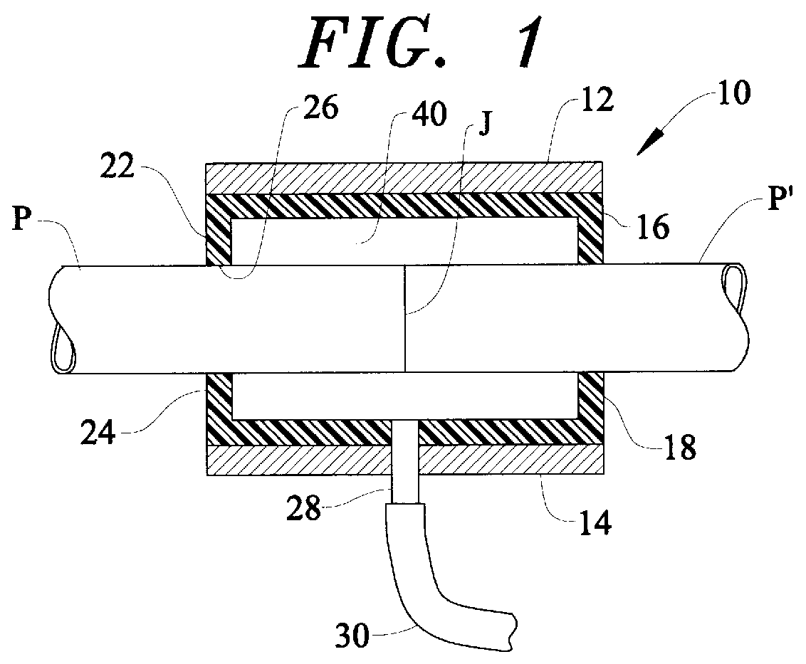
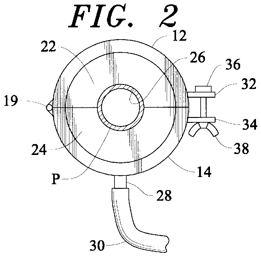
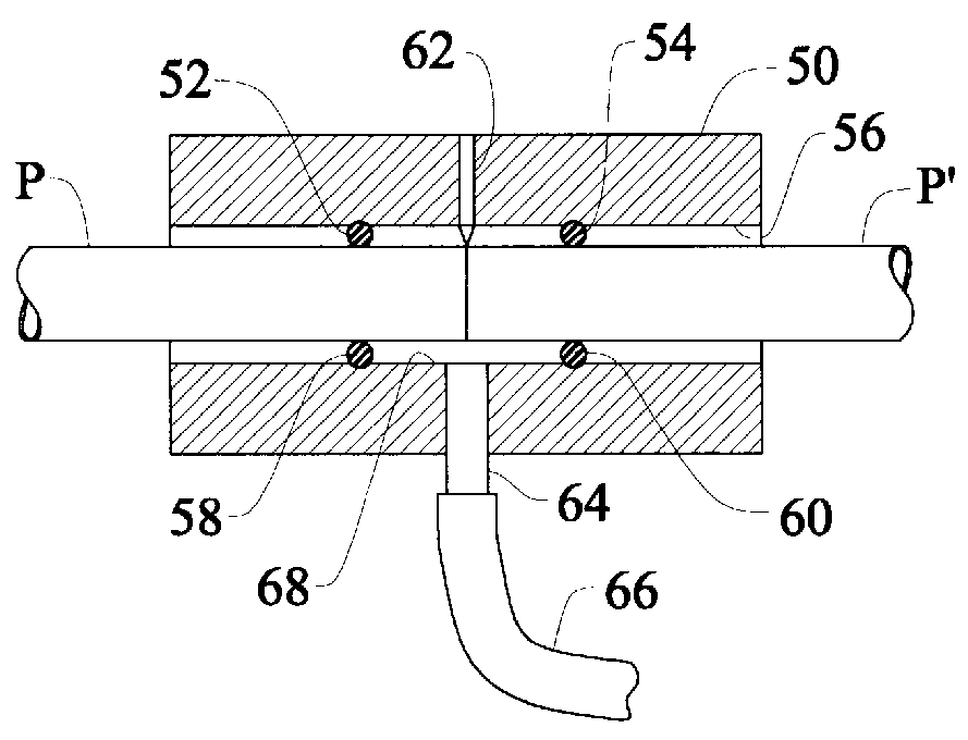
The device according to the present invention is intended to connect to the pipeline at the site of the weld, and to sample the leakage inherent at the weld site by creating a sealed chamber enclosing the weld site but in fluid communication with the flowing purge gas through the inherent leakage at the butt joint of the two pipe ends being welded. When the two pipes are prepared for welding, their ends are squared as precisely as possible, and cleaned to remove any burrs or foreign material, but even so, some inert gas passes between the two butted pipe ends. By providing seals with the exterior of the pipe both upstream and downstream of the weld site, an annular chamber is formed into which the purge gas leaks, and at the same pressure as is found on the interior of the pipeline. The seals ensure that the gas does not escape from the chamber. The chamber is also connected to a pressure gauge such as a Magnehelic in order to sample the pressure of the flowing gas and adjust the pr...


PUM

PropertyMeasurementUnit
Pressureaaaaaaaaaa

Abstract

A method and device for sampling the pressure of inert purge gas flowing in two pipes to be welded at a joint comprising a sleeve for encircling the pipes during their coaxial alignment in end to end abutment, and an associated element with the sleeve forming a sealed chamber surrounding the joint and receiving gas that leaks out from the joint at the same pressure as the gas in the pipes, and a connection for connecting the chamber for measuring the pressure of the gas therein as an indication of the pressure of the gas flowing in the pipes; the method includes clamping the device around the pipes or sliding the pipes into the device.

Description

This invention relates to an attachment for sampling an inert purge gas pressure at a weld site. More particularly, the invention relates to an attachment which may be used with an orbital welding apparatus for measuring the pressure of an inert purge gas flowing in a pipeline to be welded.BACKGROUND AND OBJECTS OF THE INVENTIONOrbital welding machines have become quite popular for welding pipelines, and especially for the welding of stainless steel pipelines as are commonly run in large plants, such as plants for manufacturing semiconductors. Stainless steel pipelines are used to carry a great variety of gaseous and liquid materials through a plant, and the construction of such pipelines requires the welding of a large number of fittings and long lengths of high purity stainless steel pipe. The quality of weld required in such applications mandates a reproducible weld of uniformly high quality, and orbital welding machines have been developed for just such applications.Orbital weld...

Claims


Application Information

Patent Timeline
IPC IPC(8): B23K9/028B23K9/32G01M3/28
CPCB23K9/0282G01M3/2884G01M3/2861B23K9/325
Inventor BAREFOOT, BYRON G.
Owner BAREFOOT BYRON G
Why Eureka
Try Eureka