Sliding yardsticks fingerprint enrollment and verification system and method

US6075876AInactive Publication Date: 2000-06-13DRAGANOFF GEORGI HRISTOFF

Image

  • Sliding yardsticks fingerprint enrollment and verification system and method
  • Sliding yardsticks fingerprint enrollment and verification system and method
  • Sliding yardsticks fingerprint enrollment and verification system and method

Examples


Embodiment Construction

A general block diagram of a fingerprint enrollment and verification system is shown in FIG. 7. A fingerprint image scanner 8 translates the applied finger fingerprint image into a standard video signal. That video signal is applied to a video frame grabber 9. The video frame grabber 9 acquires video frames acquires, extracts fingerprint images of necessary pixel number size as required by the two parts of the fingerprint enrollment and verification algorithm and saves them into memory 11, under the control of a central processing unit 10. It is preferable if the frame grabber 9 had the ability to extract the exact pixel number size images before they are saved in memory 11, but it is not a problem if it saves images of standard size in memory 11, and the images necessary for the purposes of enrollment and verification are extracted later with the necessary size from those saved into memory 11.

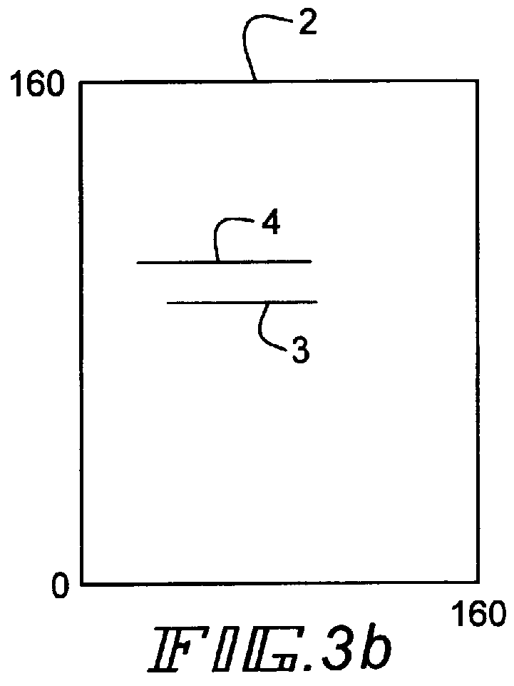
FIG. 1 shows windows 1 and 2 which represent the sizes in pixels of the two images. The im...


PUM


Abstract

A fast position tolerant and economical fingerprint verification algorithm and software implementation is disclosed. The algorithm has very important advantages in comparison to existing fingerprint verification algorithms like minutia extraction or full image analysis based on a series of two dimensional fast Fourier transforms (FFT's) and two dimensional cross correlation in speed, compactness of the biocript and finger positioning for verification. It is based on a small "yardstick" pattern being moved inside the image to be verified, and when a match is found the rest of the verification process is started. The software code implements the algorithm in the most efficient way for utilization on a digital signal processor architecture. A main area of application is in fingerprint identification and verification, but it could be implemented with same success in other image verification systems like iris, eye, face etc., where two images should be compared. The algorithm is adaptive, so various false acceptance and false rejection coefficients could be utilized very easily. It also produces a very compact biocript, which leads to better memory utilization in fingerprint databases.

Description

Most popular with fingerprint verification devices vendors method used is the minutia based verification. This is also the oldest method used by the FBI and other government agencies and in other countries around the world. It is well established understood and standardized. There is an ANSI (American National Standards Institute ) standard for "Data Format for the Interchange of Fingerprint Information", describing a common format for interchange of minutia based fingerprint data. Minutia data represents four categories of fingerprint characteristic points: ridge ending, bifurcation, compound (trifurcation or crossover ) and type undetermined. Ridge ending occurs when a friction ridge begins or ends within the fingerprint and without splitting into two or more continuing ridges, and the ridge must be longer than it is wide. A bifurcation occurs when a ridge divides or splits to form two ridges that continue past the point of division for a distance that is at least equal to the spa...

Claims


Application Information

Patent Timeline
13 Jun 2000
Publication
US6075876A
IPC
G06K9/00
CPC
G06K9/00067; G06V40/1347
Inventors
DRAGANOFF, GEORGI HRISTOFF