FM multiplex broadcasting receiver for receiving RDS and DARC signals

a broadcasting receiver and multiplex technology, applied in the direction of simultaneous amplitude and angle demodulation, broadcast system types, radio data systems/radio broadcast data systems, etc., can solve the problem of inability to simply use and the number of external components is undesired. increase, and the difficulty of simple use of a single crystal resonator

Inactive Publication Date: 2000-06-27
SEMICON COMPONENTS IND LLC
View PDF7 Cites 4 Cited by
  • Summary
  • Abstract
  • Description
  • Claims
  • Application Information

AI Technical Summary

Problems solved by technology

7.2 MHz), it is difficult to simply use a single, common crystal re...

Method used


Image

  • FM multiplex broadcasting receiver for receiving RDS and DARC signals
  • FM multiplex broadcasting receiver for receiving RDS and DARC signals
  • FM multiplex broadcasting receiver for receiving RDS and DARC signals

Examples


Embodiment Construction

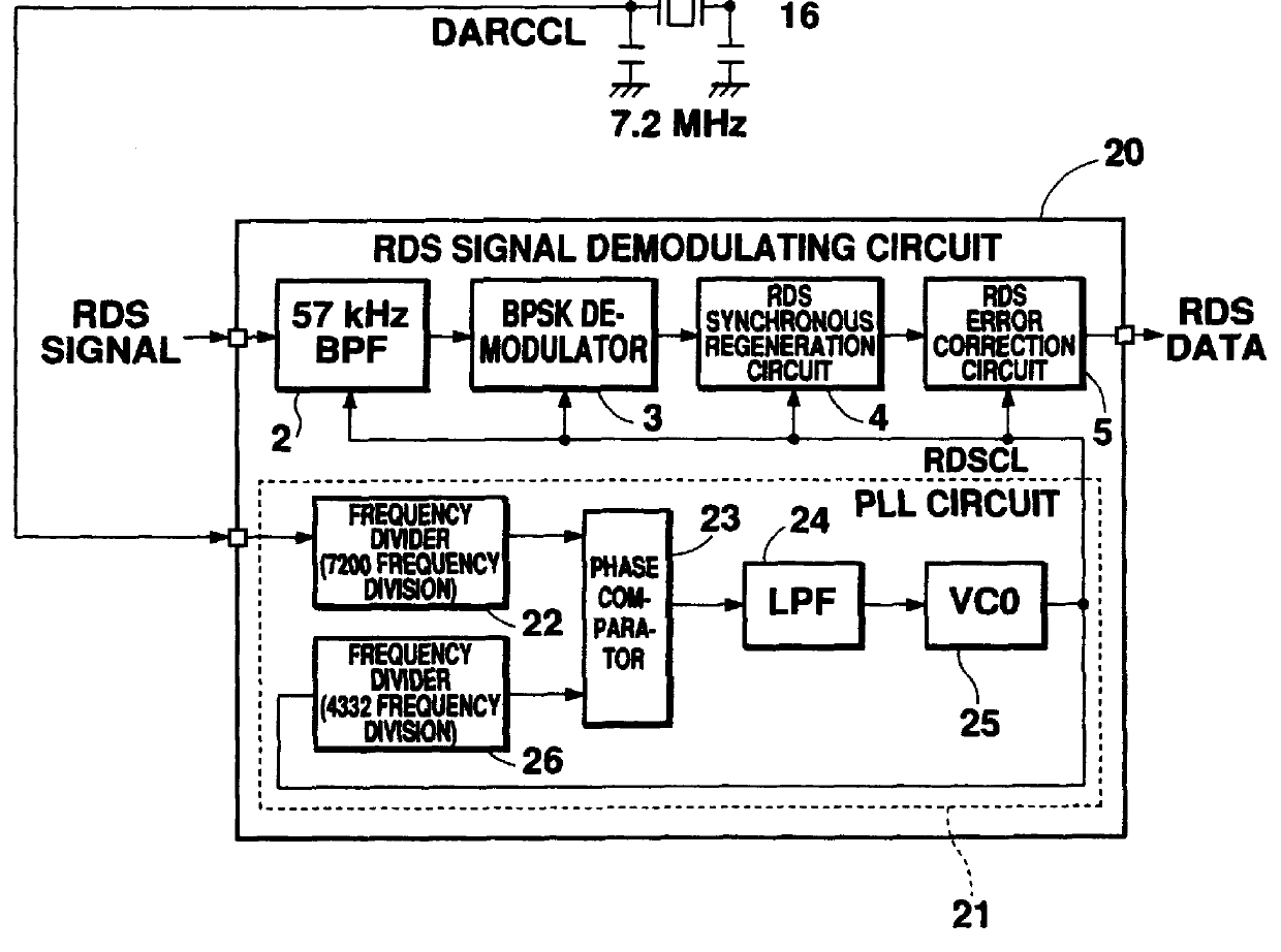
FIG. 1 is a block diagram showing an embodiment of the present invention. More specifically, FIG. 1 shows the principal part of a receiver capable of receiving FM multiplex broadcasting of both the RDS and DARC systems.

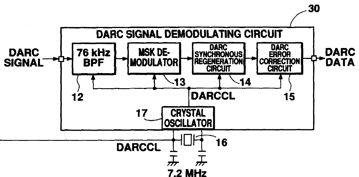
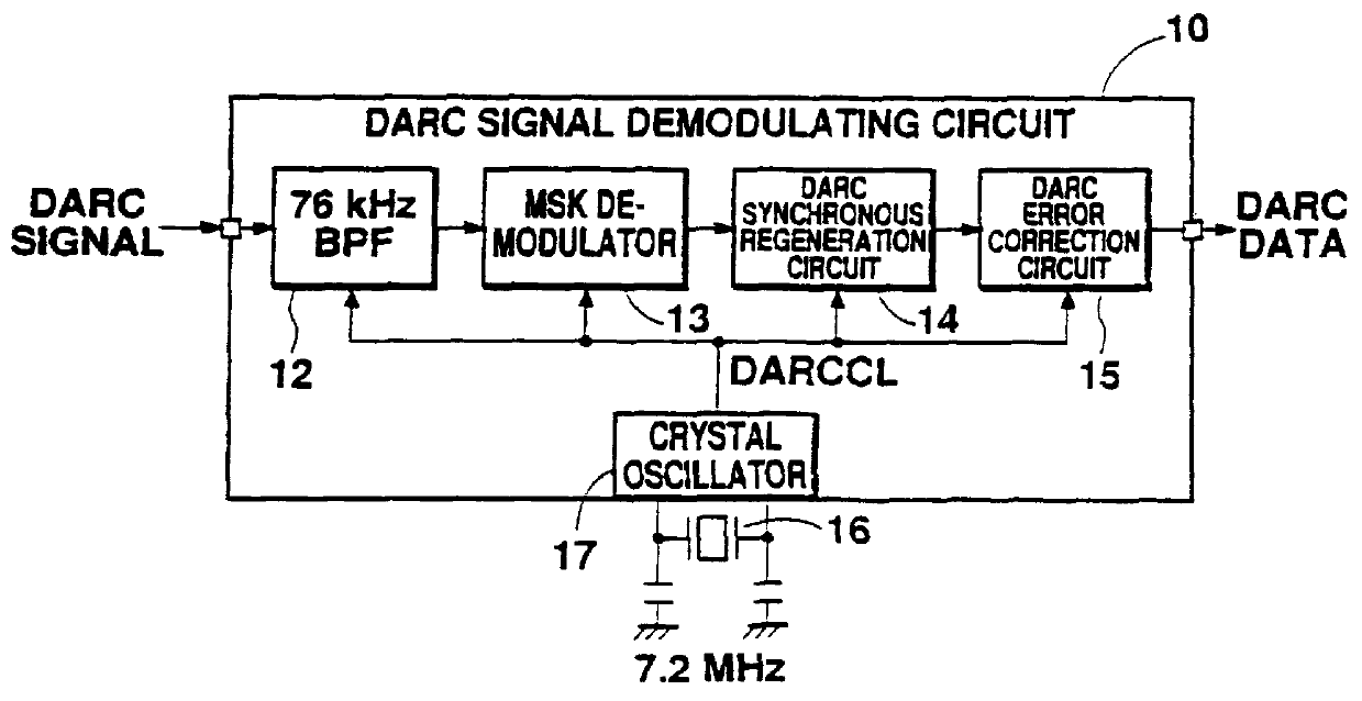
The receiver shown in FIG. 1 comprises an RDS signal demodulating circuit 20 in LSI form and a DARC signal demodulating circuit 30 which also in the form of an LSI. The constitution of the DARC signal demodulating circuit 30 is the same as the constitution shown in FIG. 3. More specifically, the DARC signal demodulating circuit 30 comprises a 76 kHz bandpass filter 12., a MSK demodulator 13, a DARC synchronous regeneration circuit 14, a DARC error correction circuit 15, and a crystal oscillator 17. A crystal resonator of 7.2 MHz 16 for generating a reference clock DARCCL is connected as an external component.

The RDS signal demodulating circuit 20 meanwhile comprises a 57 kHz bandpass filter 2, a BPSK demodulator 3, an RDS synchronous regeneration circuit 4, and an RDS...


PUM


Abstract

A receiver is provided capable of receiving both RDS (Radio Data System) and DARC (DAta Radio Channel) system FM multiplex broadcasting. An RDS signal demodulating circuit is provided with a PLL circuit which comprising a first frequency divider for dividing an output of a crystal oscillator, a phase comparator for inputting an output of the first frequency divider, a low-pass filter connected with the phase comparator, a VCO connected with the low-pass filter, and a second frequency divider for dividing an output of the VOC and outputting the divided output signal to the phase comparator. An output of the VCO is transmitted as a reference clock RDSCL for demodulation of an RDS signal.

Description

1. Field of the InventionThe present invention relates to a receiver which is capable of receiving both RDS (Radio Data System) or DARC (DAta Radio Channel) FM multiplex broadcasting signals.2. Description of the Related ArtIn FM multiplex-broadcasting, the RDS system is common in Europe, while the DARC system prevails in Japan.A typical RDS signal demodulating circuit 1, such as shown in FIG. 2, is composed of a bandpass filter BPF 2 for passing only signal components in a band centering around 57 kHz of an RDS modulated signal received, a BPSK demodulator 3 for performing BPSK demodulation of an output signal of the bandpass filter BPF 2, an RDS synchronous regeneration circuit 4 for performing synchronous regeneration based on a demodulated signal, an RDS error correction circuit 5 for detecting errors of RDS data demodulated, correcting these errors, and outputting the corrected RDS data, and a crystal oscillator 7 which generates a reference clock RDSCL due to the connection wi...

Claims


Application Information

Patent Timeline
IPC IPC(8): H04B1/16H04H1/00H03L7/06H04L7/033H03J7/18H04H40/18
CPCH04B1/1646H04H40/18H03L7/06H04L7/0331H04H2201/13H03D5/00
Inventor KANEKO, HIROSHI
Owner SEMICON COMPONENTS IND LLC
Why Eureka
Try Eureka