Permanent magnet generator

a permanent magnet generator and generator technology, applied in the direction of mechanical energy handling, magnetic circuit rotating parts, magnetic circuit shape/form/construction, etc., can solve the problems of high loss, high cost of operation, and unit failure prematurely, so as to improve longevity and durability.

Inactive Publication Date: 2000-07-11
PACIFIC SCI ELECTRO KINETICS DIV
View PDF4 Cites 50 Cited by
  • Summary
  • Abstract
  • Description
  • Claims
  • Application Information

AI Technical Summary

Benefits of technology

Accordingly, it is a general object of the present invention to provide a ge...

Problems solved by technology

Because the drill head could be up to five miles away from the surface, extendible power feeders have proven not only costly to operate, but also given to extremely high losses.
A major disadvantage is that such units tend to fail prematurely.
Premature failure results from leaks of drilling fluid into the generator housing.
The drilling fluid, w...

Method used


Image

  • Permanent magnet generator
  • Permanent magnet generator
  • Permanent magnet generator

Examples


Embodiment Construction

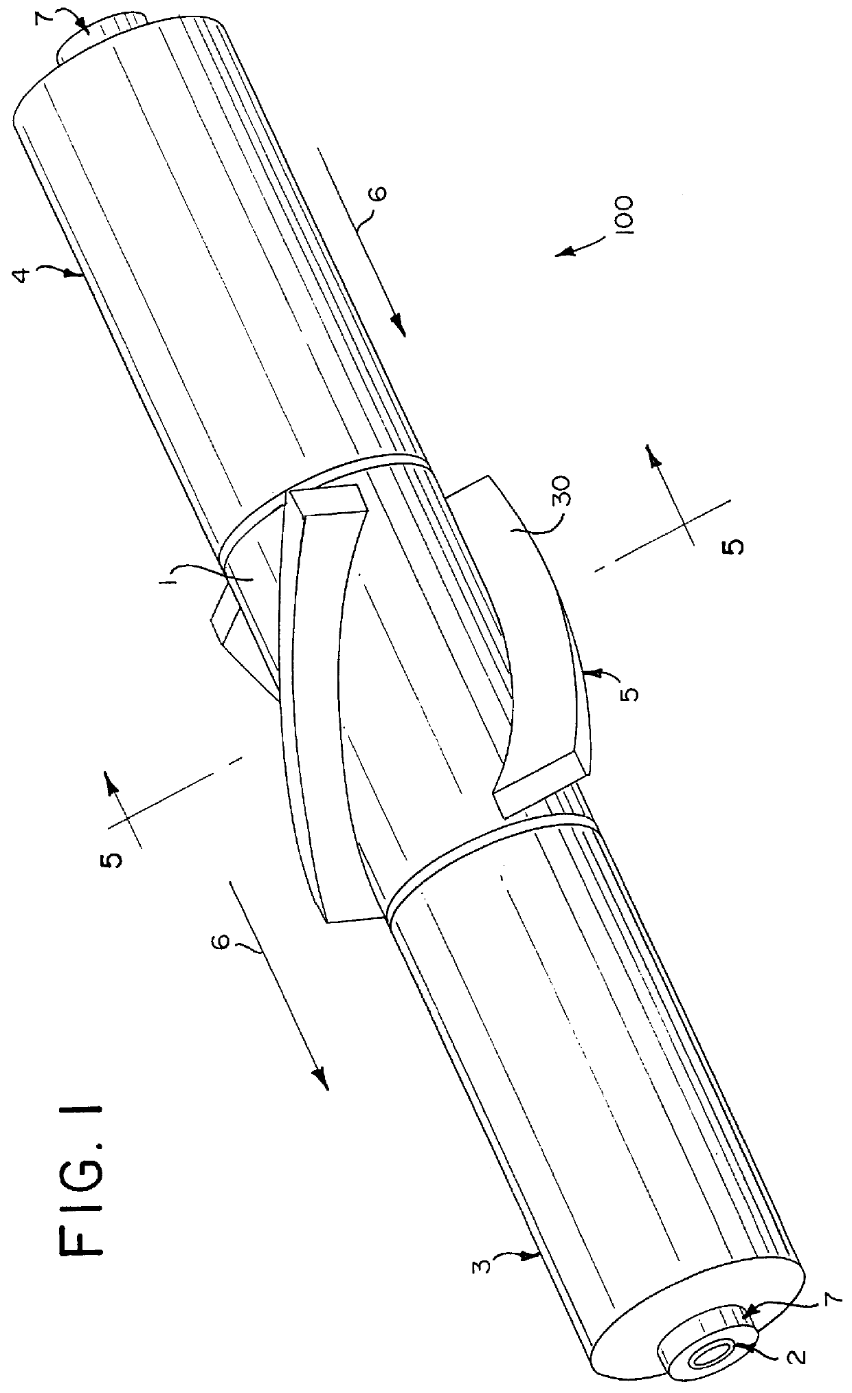
Reference is now invited to FIG. 1 which is a perspective view of a permanent magnet generator 100 according to the invention. As shown in FIG. 1, a permanent magnet generator 100 according to the invention includes a magnetic field assembly 1. The magnetic field assembly 1 is supported on a shaft 2, which runs through the magnetic field assembly 1. The magnetic field assembly 1 is adapted to rotate about the shaft 2 in direct contact with the external environment. For example, when the permanent magnet generator 100 is used in an oil exploration well, the magnetic field assembly 1 is adapted to rotate about the shaft 2 in direct contact with drilling fluid or "mud." The shaft 2 also runs through stationary armature assemblies 3, 4. The stationary armature assemblies 3, 4 are positioned on opposite sides of the magnetic field assembly 1 and are axially spaced therefrom. Accordingly, in the present invention, unlike existing in devices, an axial air gap is provided between the armatu...


PUM


Abstract

A permanent magnet generator is described. The generator includes a shaft which defines a longitudinal axis. A rotatable magnetic field assembly is mounted on the shaft and adapted for rotation about the shaft. The magnetic field assembly includes a plurality of axially magnetized magnets which are retained in a cavity about the shaft for generating an axial magnetic flux. A plurality of vanes are mounted on the magnetic field assembly housing for rotating the magnetic field assembly about the shaft when a fluid flows past the vanes. A stationary armature assembly is also located around the shaft in a position axially spaced from the magnetic field assembly. The armature assembly generates AC power when the magnetic field assembly is rotated. The stationary armature assembly includes an armature housing. An axial bore is formed through the armature housing for receiving the shaft. The armature housing defines a cavity about the axial bore in which a plurality of laminated bars are retained. A plurality of electrically conductive wires are wrapped around the laminated bars to form coils.

Description

The present invention relates to electrical power generation and in particular to electrical power generation in applications that restrict diametrical space, such as oil exploration wells.BACKGROUND TO THE INVENTIONRecent practices in oil exploration require that electric power be made available at the far end of an oil exploration well to power a variety of instruments that aid in navigating the drill head. Because the drill head could be up to five miles away from the surface, extendible power feeders have proven not only costly to operate, but also given to extremely high losses. Exploration companies and drill operators have therefore come to require that electric power be generated remotely at the end of the oil exploration well.The typical remote power generation unit includes a turbine and an electrical generator which is coupled to the turbine via a transmission shaft. The turbine is positioned within the well in direct contact with the drilling fluid whereas the electrical...

Claims


Application Information

Patent Timeline
IPC IPC(8): H02K7/14H02K21/12H02K21/24H02K21/00
CPCH02K7/14H02K21/24
Inventor RAAD, BERNARD A.
Owner PACIFIC SCI ELECTRO KINETICS DIV
Why Eureka
Try Eureka