Incremental sensor of speed and/or position for detecting low and null speeds

a technology of increasing speed and position sensor, applied in the direction of instruments, galvano-magnetic hall-effect devices, manufacturing tools, etc., can solve the problems of mechanical constraints, sensor adaptation to the use of a toothed surface with small amount of pitch, and the dimension of the moving component is limited by its cost, so as to reduce thickness and increase play

Inactive Publication Date: 2000-07-11
MOVING MAGNET TECH
View PDF1 Cites 28 Cited by
  • Summary
  • Abstract
  • Description
  • Claims
  • Application Information

AI Technical Summary

Benefits of technology

According to a preferred mode of implementation the magnet, the Hall-effect gaussmeter and the associated electronic circuits are integrated in a housing made of plastic made by cast molding. This mode of implementation allows one to precisely position the probe with respect to the magnet and to increase the play between this cast molded assembly and the toothed wheel because of the reduced thickness or of the absence of plastic between the Hall-effect gaussmeter and the magnet.

Problems solved by technology

Such sensors are sensitive to different external disturbances, and the dimensions of the moving component are limited by its cost.
Such sensors are poorly adapted for the use of a toothed surface with small amount of pitch.
In order to reduce the detection pitch it is therefore necessary to move the magnet closer to the toothed surface, which creates mechanical constraints which are difficult to adhere to during fabrication of very great numbers of devices.
Such sensors are particularly poorly adapted for the detection of low speeds, even more so for the detection of position, because of the average increased value of the field with respect to the amplitude of its modulation.
Therefore there might be some detection errors at the start.
These two solutions require complex electronic circuits, or large area silicon chips, which greatly increase the cost of the sensors, particularly in the case when one is using a differential sensor.
However, such a sensor is no longer completely satisfactory.
This increase of the distance also has an unfavorable impact on the amplitude of the detected view, and the sensor is for this reason sensitive to parasitic magnetic fields.
This diameter is already too small to allow economic implementation over a length of 4 mm.
It is also quite disadvantageous to remove the mass of the magnet from the OZ axis on which one can produce maximum modulation; but this is inevitably produced with tubular magnets of the prior state of the art.
The point of the null field being arranged too far from the side of the magnet, the Hall-effect gaussmeter must be moved further from the magnet which requires an increase of the air gap and causes a reduced sensitivity of the sensor.
The sensor according to this state of the art is therefore not compatible with practically feasible miniaturization.
In addition, control of the exact position of the Hall-effect gaussmeter with respect to the cancellation zone of the field component along OZ is extremely delicate when the field gradient is increased, and this control is hardly compatible with the proposed devices.

Method used


Image

  • Incremental sensor of speed and/or position for detecting low and null speeds
  • Incremental sensor of speed and/or position for detecting low and null speeds
  • Incremental sensor of speed and/or position for detecting low and null speeds

Examples


Embodiment Construction

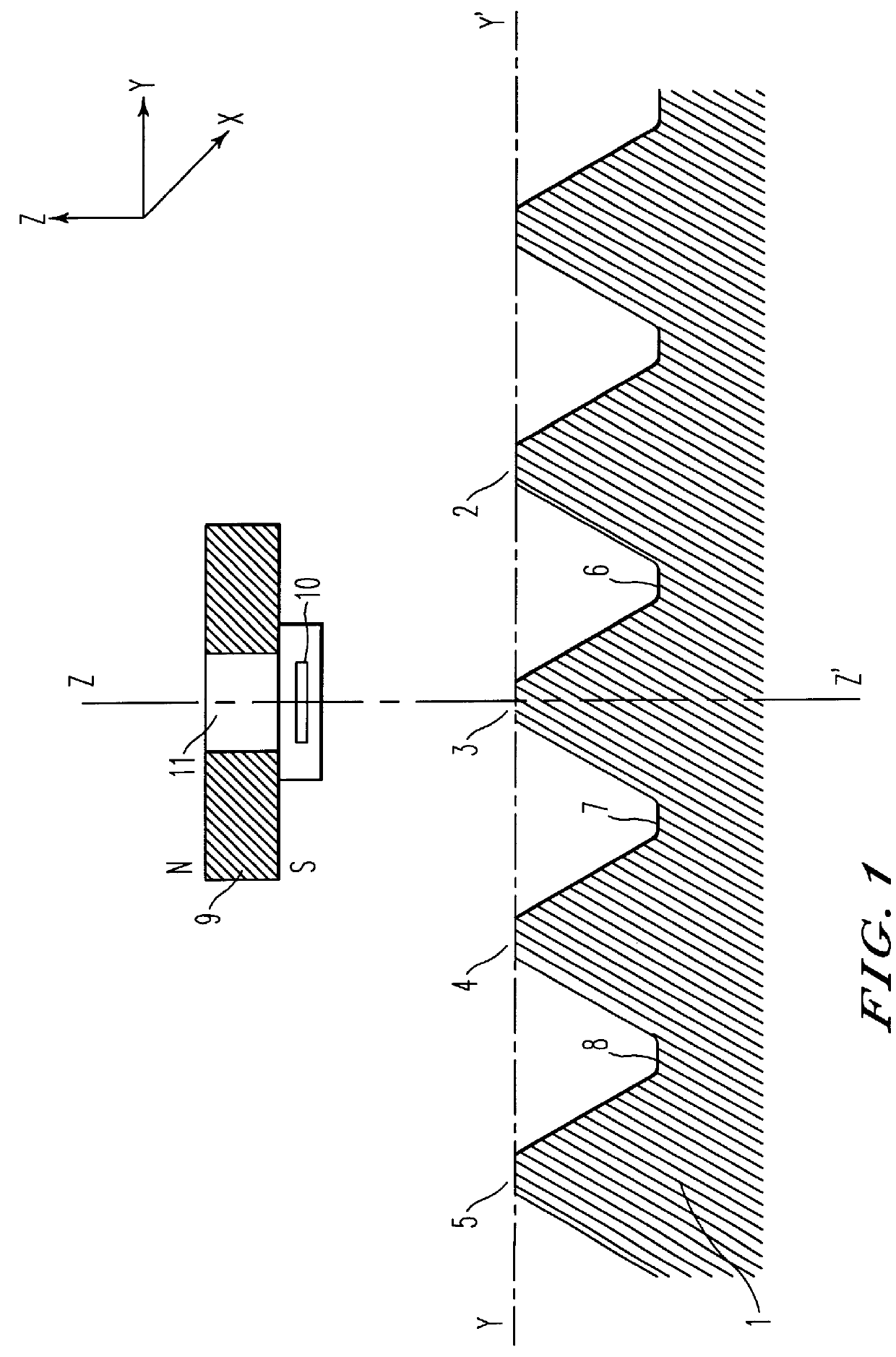
FIG. 1 represents a schematic view of the sensor in a mode of implementation for detecting speed and angular position.

The sensor includes a toothed wheel (1) which has a large number of teeth (2, 3, 4, 5) and of intervening holes (6, 7, 8). The wheel (1) is made of a soft magnetic material.

The sensor also includes a magnet (9) magnetized along the ZOZ' radial direction. The magnet therefore has one of its poles directed in the direction of the toothed wheel (1) and the other pole in the opposite direction. A Hall-effect gaussmeter (10) is arranged on the ZOZ' axis, between the toothed wheel (1) and the permanent magnet (9).

The magnet (9) is a disk-shaped magnet of diameter D and of thickness L. By way of example the magnet is of the Samarium-cobalt type having a diameter of 7 mm and a thickness L of 2 mm.

The magnet (9) is perforated with a circular air gap (11) having a diameter of 1.4 mm.

The average distance between the top of a tooth and the magnet is 1.6 mm and the height of the ...


PUM

PropertyMeasurementUnit
diameteraaaaaaaaaa
diameteraaaaaaaaaa
diameteraaaaaaaaaa

Abstract

This invention pertains to an incremental sensor of position and/or speed, of the type which includes a moving component made of a soft material that has at least one moving tooth in a direction OZ with respect to a permanent magnet magnetized along the direction OY, which is approximately perpendicular to the OZ axis, and a probe which is sensitive to the direction and strength of the magnetic field, such as a Hall-effect gaussmeter, arranged in the air gap between the magnet and the tooth of the moving component so that its axis of greatest sensitivity is approximately oriented along the OZ axis. The Hall-effect gaussmeter is located near a singular point of the OZ axis where the average value of the magnetic field is weak and preferably less than .+-.20 mT and approximately equal to the average value of the alternating field of the integrated circuit connected to the Hall-effect gaussmeter. The permanent magnet can also be laser trimmed to achieve the desired operation in the Hall-effect gaussmeter.

Description

BACKGROUND OF THE INVENTION1. Field of the InventionThis invention pertains to an incremental speed and / or position sensor which utilizes a probe which is sensitive to the direction and amplitude of a magnetic field, a Hall-effect gaussmeter for example, for the detection of speed and / or position, which is capable of detecting speeds down to a low value corresponding to a null speed, and which can implement a laser trimming operation to enhance operation in the sensor.2. Discussion of the BackgroundThe magnetic probe delivers an electric signal as a function of the magnetic field crossing it. The state-of-the-art speed sensors are designed in such a manner that the displacement of a moving component will cause a variation of the magnetic field. Subsequently in the description we will use the term "Hall-effect gaussmeter" to designate a sensor which is sensitive to the direction and amplitude of the magnetic field, which provides an electric signal as a function of the direction and ...

Claims


Application Information

Patent Timeline
Patent Type & Authority Patents(United States)
IPC IPC(8): G01B7/14G01B7/30G01R33/06H01L43/06
CPCG01R33/06G01B7/14G01B7/30H01L43/06H10N52/00G01D5/145G01D5/147
Inventor OUDET, CLAUDE
Owner MOVING MAGNET TECH
Why Eureka
Try Eureka