Self-healing network

Inactive Publication Date: 2000-07-11
TELEFON AB LM ERICSSON (PUBL)
View PDF7 Cites 104 Cited by
  • Summary
  • Abstract
  • Description
  • Claims
  • Application Information

AI Technical Summary

Problems solved by technology

In such a ring the bottleneck is constituted by the speed of the processing electronics, and the ban

Method used


Image

  • Self-healing network
  • Self-healing network
  • Self-healing network

Examples


Embodiment Construction

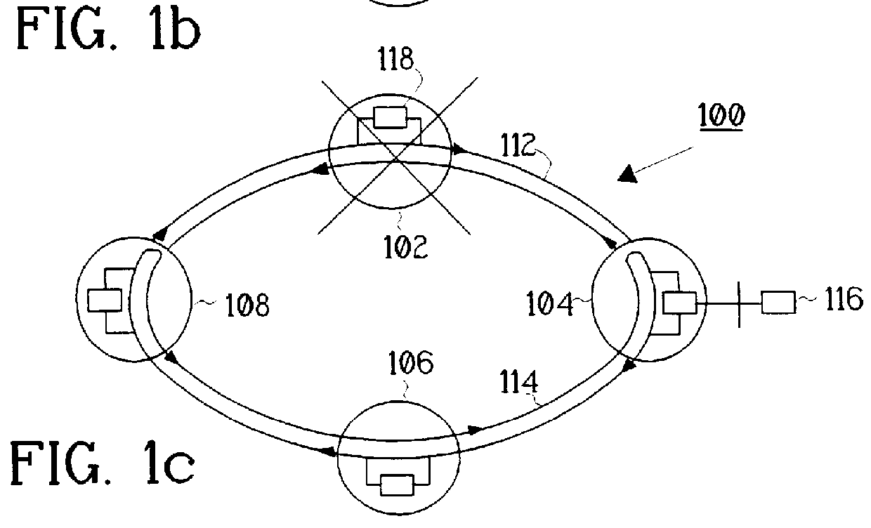
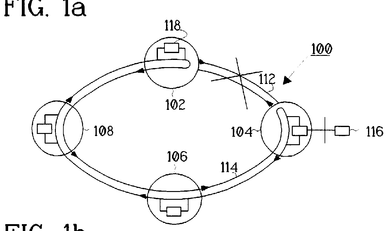
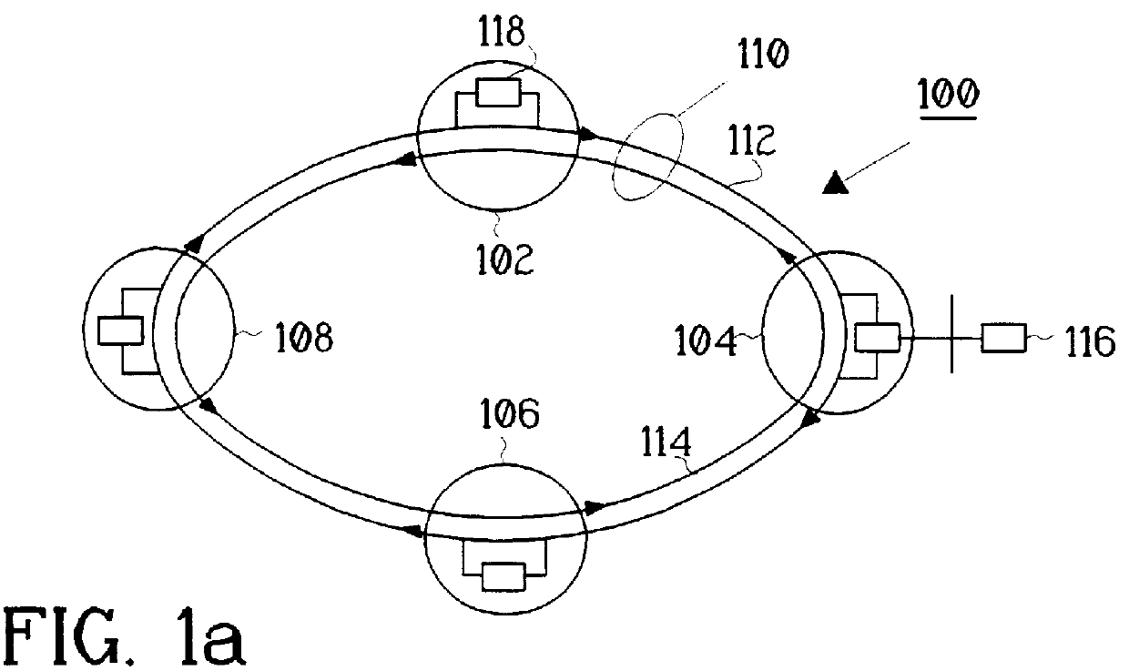
FIG. 1a shows a schematic view of a communication ring network 100 where the present invention may be implemented. The network 100 has a number of N nodes 102-108 connected to each other by transmission links e.g. optical links 110. N stands for at least three, meaning that the network 100 consists of at least three nodes. The transmission links 110 comprise; a first transmission link or working ring 112, and a second transmission link or a protection ring 114. The working ring 112 is carrying traffic in one transmission direction, clockwise in the figure. The protection ring 114 is carrying traffic in the opposite transmission direction, counter-clockwise in the figure. The traffic can, for example be electric, optical energy or wavelength channels. If wavelength channels are used, there are M optical channels transmitted where M can be less, equal or more than N nodes. FIG. 1a also shows the communication network 100 in its normal working state, where the M optical channels are tr...


PUM


Abstract

PCT No. PCT/SE96/00794 Sec. 371 Date May 27, 1998 Sec. 102(e) Date May 27, 1998 PCT Filed Jun. 18, 1996 PCT Pub. No. WO97/01907 PCT Pub. Date Jan. 16, 1997A communication network system having at least three nodes, which are interconnected by transmission links carrying traffic to and from the nodes. The transmission links are divided into a working ring and a protection ring where the working ring and the protection ring can transmit traffic in opposite directions. A node is able to detect when an error occurs in the surrounding transmission links or the node itself. Each node can, by itself, divert traffic from the working ring to the protection ring and/or from the protection ring to the working ring. A recovery action is performed when the error is healed.

Description

TECHNICAL FIELD FOR THE INVENTIONThe present invention relates to an apparatus and a method for a communication network, more particular to a self-healing network.DESCRIPTION OF RELATED ARTIn a conventional self-healing ring architecture, synchronous digital hierarchy SDH or synchronous optical network SONET, utilizing add / drop multiplexer (ADM), the optical fiber is only used as point to point link and optical-electrical conversion is operated at each node. In such a ring the bottleneck is constituted by the speed of the processing electronics, and the bandwidth-sharing is characteristic for this architecture leads to a limitation of the network capacity.In the article "Self-Healing Ring Network Architecture Using WDM for Growth", ECOC 92, Tu P1.16, by Aly Elrefaie, is presented a self-healing ring network. It is described by a 2-fiber WDM ring network where N-1 local offices are originating traffic that is served by a single hub. Transmission on both fiber rings is identical excep...

Claims


Application Information

Patent Timeline
IPC IPC(8): H04L12/437H04L1/22H04Q11/00H04J14/02H04B10/07H04B10/032H04B10/035H04B10/079H04B10/27H04B10/275H04B10/296H04J3/00H04J3/08
CPCH04J14/0212H04J14/0283H04J14/0291H04L1/22H04L12/437H04Q11/0062H04J14/028H04Q11/0071H04Q2011/0013H04Q2011/0043H04Q2011/0049H04Q2011/0081H04Q2011/0083H04Q2011/0092
Inventor MERLI, STEFANOTESTA, FRANCESCONORBIATO, RENATOANDREOZZI, PAOLO
Owner TELEFON AB LM ERICSSON (PUBL)
Why Eureka
Try Eureka