Method of heat treating object and apparatus for the same

Inactive Publication Date: 2000-07-18
PANASONIC CORP
View PDF36 Cites 30 Cited by
  • Summary
  • Abstract
  • Description
  • Claims
  • Application Information

AI Technical Summary

Problems solved by technology

With respect to the above heat treatment, there is an energy utilization efficiency problem in that a ratio of an amount of heat energy which is truly used to heat treat the object itself to an amount of heat energy which is supplied to the heat treatment apparatus is small.
This means that most of the supplied heat energy is wasted.
This problem leads to a high cost for the heat treatment.
Since an inlet and an outlet of the tunnel shaped heating chamber are always open to the outside, a portion of heat energy supplied to the heating chamber is lost through the inlet and the outlet.
The moving mechanism such as the conveyer is complicated and its heat capacity is large.
Thus, a large amount of heat energy is required to heat up the mechanism.
Every time the conveyer g

Method used


Image

  • Method of heat treating object and apparatus for the same
  • Method of heat treating object and apparatus for the same
  • Method of heat treating object and apparatus for the same

Examples


Embodiment Construction

The present invention will be explained below further in detail with reference to the accompanied drawings.

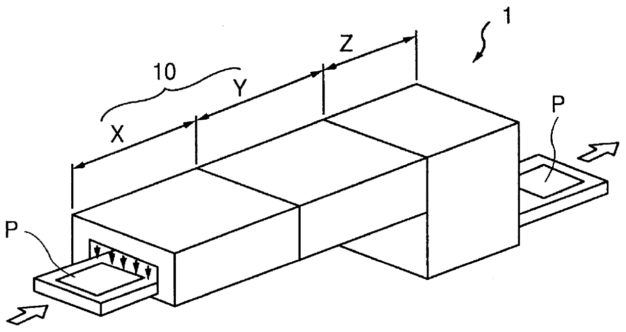
FIG. 1 schematically shows a perspective view of a heating apparatus 1 which is used for the method of the prevent invention. The heating apparatus 1 comprises of a heating zone X, a thermally treated zone Y and a cooling zone Z. An object P in the form of a rectangular plate is supplied to the heating zone X, as shown with the arrow, is passed through the thermally treating zone Y and the cooling zone Z, and is discharged from the apparatus 1. The heating zone X and the thermally treating zone Y form a heating chamber 10 as shown. An air curtain is provided at the inlet of the heating chamber 10 so that the inside of the heating chamber 10 is shielded from its outside. For example, the shown apparatus may be used for calcination, firing or sintering of the object P comprising a glass substrate, a ceramic substrate, a metal substrate and the like on which a film forming materia...


PUM

PropertyMeasurementUnit
Temperatureaaaaaaaaaa
Pressureaaaaaaaaaa
Heataaaaaaaaaa

Abstract

In the heat treating method and the heat treatment apparatus of the object, the object is heat treated while it is being floated by gas expelled toward the object from a position below the object in the heating chamber.

Description

1. Field of the InventionThe present invention relates to a method and an apparatus for heat treating an object, and particularly for heat treating a starting material or an intermediate product for the production of a final product or for the treatment of various products.2. Related ArtVarious heat treatments are used for the production of various products. For example, by heat treatment of an object a number of effects can be obtained such as drying, dehydration, calcination, reaction acceleration, surface modification and so on. In order to improve the efficiency of the heat treatment, an object to be heat treated is passed through a heating chamber in the form of a dome or a tunnel while the object is moved using a conveyer.An apparatus which carries out such a heat treatment includes a heating zone where temperature of a object is increased to a temperature at which a thermal treatment is started, and a thermally treating zone where such an object of which temperature has been ...

Claims


Application Information

Patent Timeline
IPC IPC(8): F27B9/24F27B9/00F27B9/10
CPCF27B9/2476F27B9/10Y10S29/081
Inventor NAKA, HIROYUKIMORITA, MAKOTOTSUTSUI, YUJINISHIKI, NAOMIISHIO, HIROAKI
Owner PANASONIC CORP
Why Eureka
Try Eureka