Particle sensor with cooled light trap and related method

a light trap and particle sensor technology, applied in particle and sedimentation analysis, measurement devices, instruments, etc., can solve the problems of reducing sensor performance, substantial problems, and a large number of microscopic airborne particles, and achieve the effect of reducing electrical noise and spurious electrical nois

Inactive Publication Date: 2000-07-18
VENTUREDYNE LTD
View PDF11 Cites 37 Cited by
  • Summary
  • Abstract
  • Description
  • Claims
  • Application Information

AI Technical Summary

Benefits of technology

Yet another object of the invention is to provide a particle sensor and method which limit the light trap surface temperature to a value which substantially eliminates, or at least sharply reduces, thermally-induced electro-optical disturbances in the sensor and spurious electrical "noise" resulting from such disturbances. How these and other objects are accomplished will become apparent from the following descriptions and from the drawings.
Other aspects of the invention involve a method for reducing electrical noise detected by an opto-electrical system in a particle sensor of the type described above and operating in ambient air at an ambient air temperature. The method includes providing a cooling apparatus in heat transfer relationship to the surface and transferring heat from the surface to the cooling apparatus at a rate which limits the surface temperature to a value which substantially eliminates--or at least sharply reduces--thermally-induced electro-optical disturbances in the sensor. And when such disturbances are reduced or eliminated, the spurious electrical noise thought to be caused thereby is also reduced or eliminated.

Problems solved by technology

Even work environments which appear to human observation to be clean--business offices, manufacturing facilities and the like--are likely to have substantial numbers of microscopic airborne particles.
While such particles are not usually troublesome to the human occupants, they can create substantial problems in certain types of manufacturing operations.
This is so since stray, "unkilled" light which finds its way to the opto-electrical system or back to the light source itself will degrade sensor performance.
But since most of the photon energy emitted by the source must be killed (that is, very little is scattered by a particle), the primary filter or surface must dissipate increasing amounts of thermal energy.

Method used


Image

  • Particle sensor with cooled light trap and related method
  • Particle sensor with cooled light trap and related method
  • Particle sensor with cooled light trap and related method

Examples


Embodiment Construction

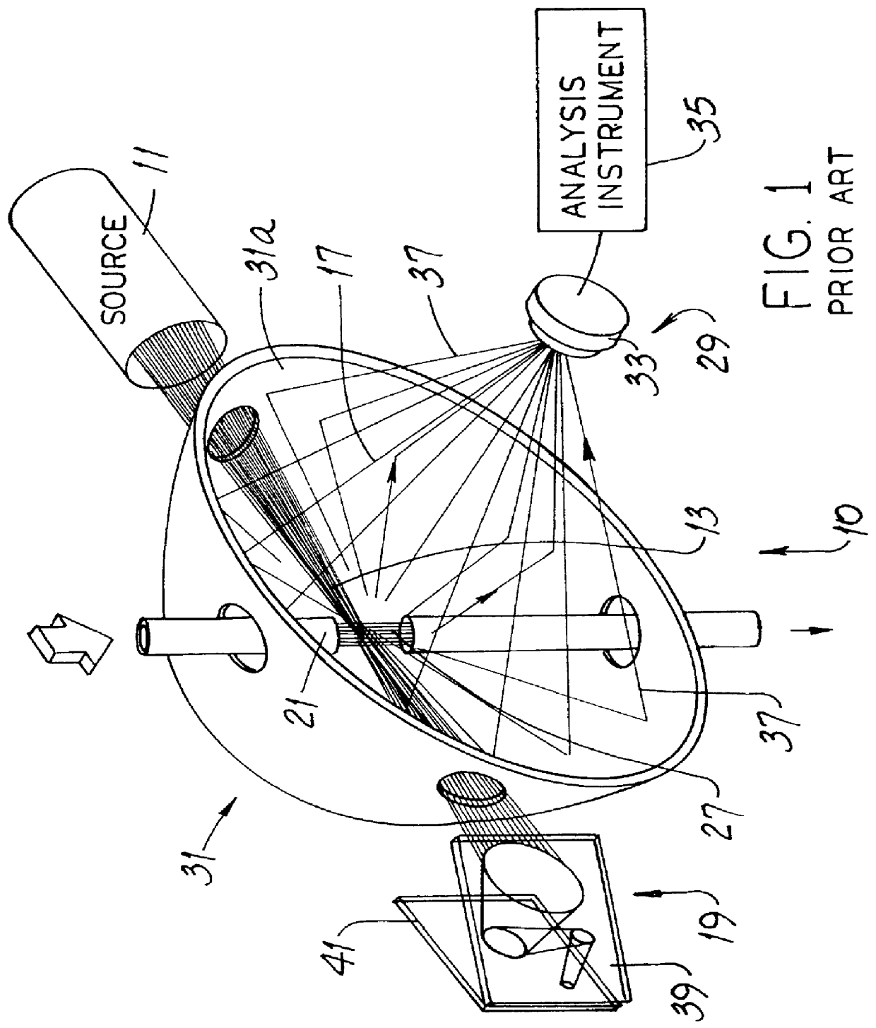
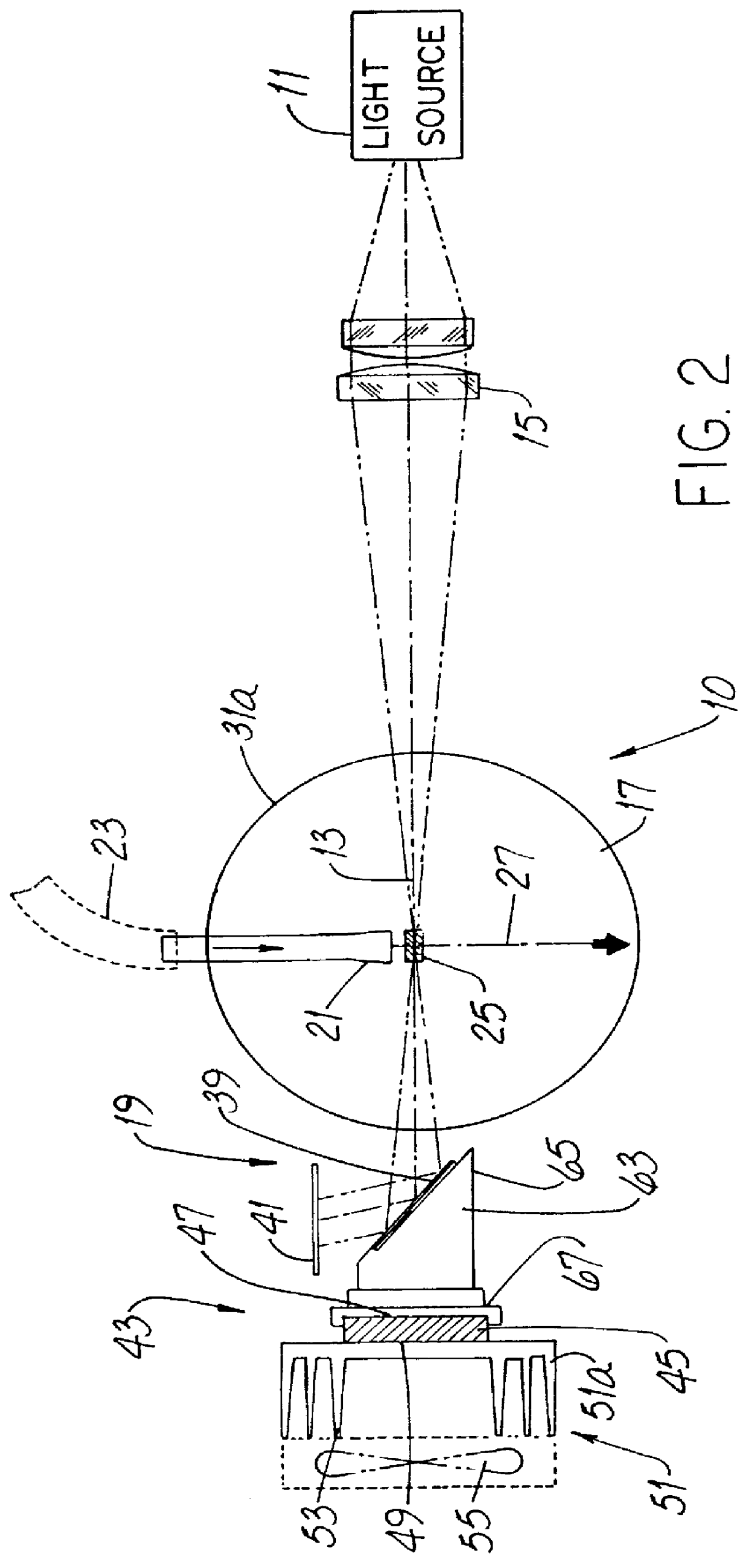
Before describing detailed aspects of the invention, it will be helpful to have an understanding of some of the features of the particle sensor 10 per se. Referring to FIGS. 1 and 2, the sensor 10 includes a light source 11 which may be embodied as a laser diode, a laser diode array or a laser diode pumped solid state laser, to name a few examples.

If the source 11 does not focus light internally and emit a very-small-diameter beam of light 13, such source 11 propagates light to a focusing component 15, e.g., a set of focusing lenses or the like. The focusing lenses focus the light to a linear, very-small-diameter beam of light 13. In either case, the beam of light 13 is projected across a cavity 17 and thence to a light trap 19.

The sensor 10 also has a nozzle 21 which is angular to the beam of light 13 and, preferably, is perpendicular thereto. A vacuum source (not shown) draws air or other gas through the nozzle 21 and exhausts such gas to room ambient. For example, ambient air fro...


PUM

PropertyMeasurementUnit
temperatureaaaaaaaaaa
volumeaaaaaaaaaa
temperatureaaaaaaaaaa

Abstract

A particle sensor operates in ambient air at an ambient air temperature and includes (a) a light source projecting a beam of light, (b) a light trap aligned with the beam of light and comprising at least one light-energy-absorbing surface at a surface temperature, (c) a nozzle flowing particle-entraining air through the beam of light, and (d) an opto-electrical system detecting light scattered by a particle. In the improvement, the sensor includes a cooling apparatus in heat transfer relationship to the surface and absorbing heat from such surface. The surface temperature is maintained at or below a value which substantially eliminates thermally-induced electro-optical disturbances in the sensor. A new method for reducing electrical noise detected by an opto-electrical system in the particle sensor includes providing a cooling apparatus in heat transfer relationship to the surface and transferring heat from the surface to the cooling apparatus at a rate which limits the surface temperature to a value which substantially eliminates thermally-induced electro-optical disturbances in the sensor.

Description

This invention relates to air quality and, more particularly, to instruments, i.e., particle sensors, for assaying airborne particulates.Particle counters (often called particle sensors) are used to detect light scattered by particles entrained in a stream of fluid, e.g., in an air stream. Such counters draw air (with particles entrained therein) from a room, for example, and flow such air along a tube and through an illuminated sensor "view volume" to obtain information about the number and size of such particles. Such information results from an analysis of the very small amounts of light reflectively "scattered" by the particle as it moves through the view volume.Such counters direct the air and accompanying particles through the view volume at a particular flow rate (often measured in cubic feet per minute) from one tube (inlet tube) across an open space (view volume) to another tube (outlet tube). In counters of this type, there is no tube wall (however transparent such wall mi...

Claims


Application Information

Patent Timeline
Patent Type & Authority Patents(United States)
IPC IPC(8): G01N15/02G01N15/00
CPCG01N15/0205
Inventor KREIKEBAUM, GERHARD
Owner VENTUREDYNE LTD
Why Eureka
Try Eureka