Radially side mounted railway car truck

Inactive Publication Date: 2000-07-25
MONSELL DALE
View PDF4 Cites 9 Cited by
  • Summary
  • Abstract
  • Description
  • Claims
  • Application Information

AI Technical Summary

Benefits of technology

The different truck design features combine to form a unique primary suspension and support system functioning effectively to permit truck swiveling while providing an essentially direct load path from each of the wheelset axle journal bearings to the rail car body. The present invention permits mi

Problems solved by technology

Relatively less progress has been made, however, in the reduction of the weight of the conventional four-wheel rail car truck which comprises the structure by which the rail car body is supported relative to the wheels.
A factor commonly contributing to the overall weight of conventional truck systems is the need to allo

Method used


Image

  • Radially side mounted railway car truck
  • Radially side mounted railway car truck
  • Radially side mounted railway car truck

Examples


Embodiment Construction

)

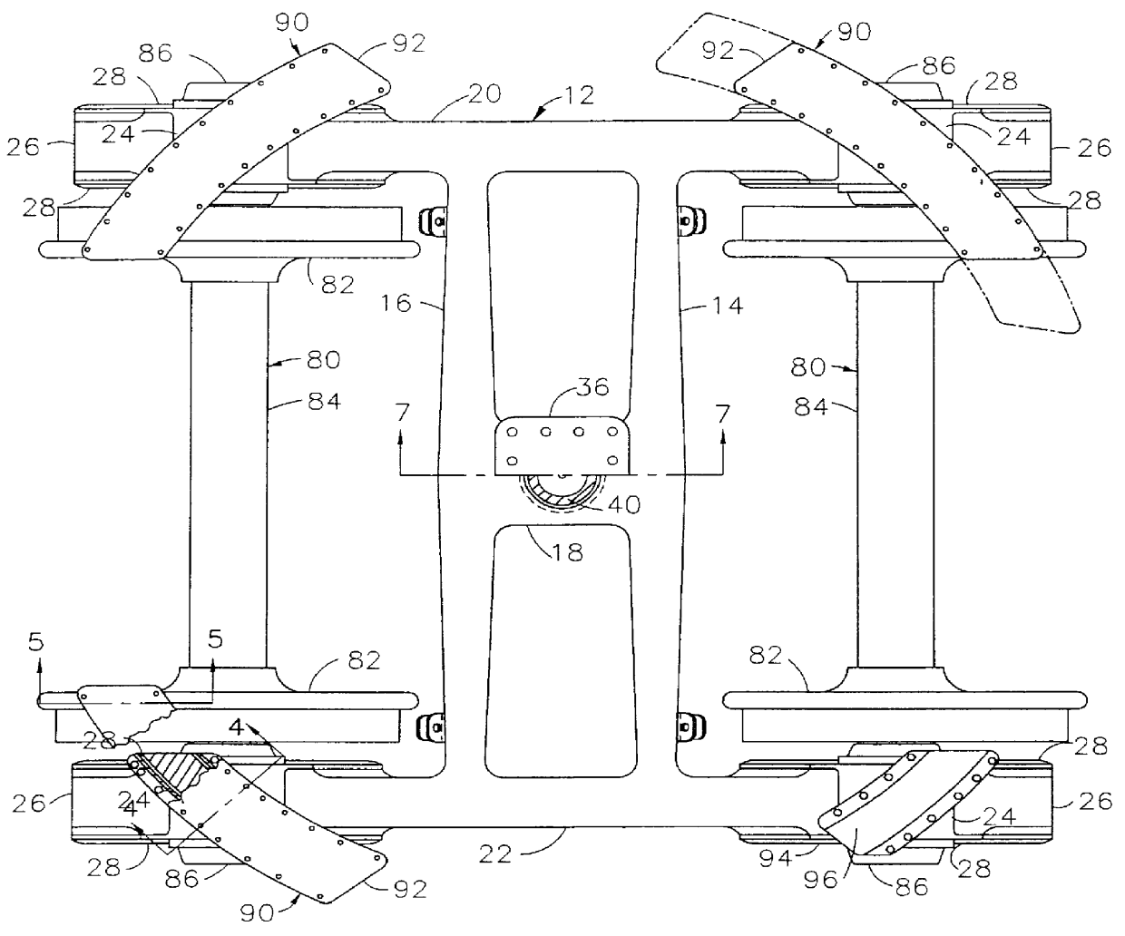
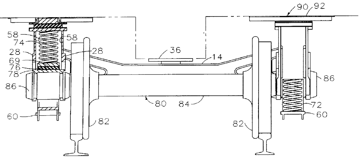
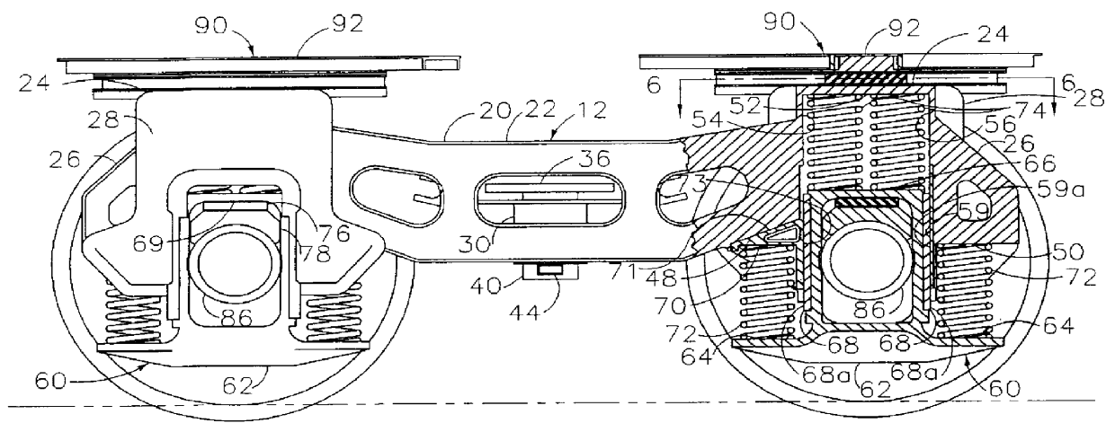
Referring to the drawing figures, the railroad car truck assembly is generally designate in FIGS. 1, 2, and 3 by the numeral 10 and includes the truck assembly frame 12 shown by the FIGS. 1, 2, and 3. Frame 12 is a rigid type frame for essentially holding the wheelsets 80 of the truck assembly 10 in the required relative horizontal position and included no heavy cross-support bolster type member. For lighter weight frame 12 uses a general I-beam type cross sectional construction of side frame sections 20 and 22 and cross-connecting structural members 14 and 16. Incorporated in the frame assembly 12 are downwardly open recesses to receive the respective four wheelset holding saddle assemblies 60, each saddle assembly 60 having supporting truck springing systems and a stabilizing wedge block member 70. The respective four radial support assemblies 90 are mounted on raised pedestals 24 at the four corners of the truck frame assembly 12 to provide sufficient clearance of the car body o...


PUM


Abstract

An improved railroad car wheel truck assembly comprises four arcuate weight bearing surfaces, one above each axle bearing, providing a direct load path such that a light weight frame can be used, each weight bearing surface being received within a matching arcuate channel mounted on the underside of the rail car body, the channels having a greater arc length that the corresponding weight bearing surface such that the wheel truck is allowed to rotate relative to the rail car body, about a central pivot pin, the wheel truck assembly further comprising a two part spring assemblies for each wheel with long springs that are always under compression and shorter springs that are compressed only when the car is under a load, each wheel spring assembly having one long spring that urges a wedge between the wheel truck frame and wheel set axle holding saddle to urge the wheel set and axle into alignment.

Description

III. BACKGROUND OF THE INVENTIONA. Field of InventionThe present invention relates generally to railroad cars and, and more particularly to a new and improved railroad car truck holding the wheels and supporting the railroad car body relative to the wheels.B. Description of Related ArtAn important design goal for railway freight cars particularly, for bulk train service, is the reduction of the tare weight of the vehicle itself. Thus the car can carry an increased weight of lading on each load trip for a given reduction in tare weight where car operation is at the maximum allowable weight on rail as determined by the wheel bearing size.Considerable progress has been made in the reduction of the weight of the body of rail cars, particularly in the case of the high utilization coal car, with the use of aluminum construction. Relatively less progress has been made, however, in the reduction of the weight of the conventional four-wheel rail car truck which comprises the structure by whi...

Claims


Application Information

Patent Timeline
IPC IPC(8): B61F5/30B61F5/00B61F5/14B61F5/02
CPCB61F5/148B61F5/301
Inventor MONSELL, DALE
Owner MONSELL DALE
Why Eureka
Try Eureka